Dual Zone Digital Location Control Unit Installation and Operation Manual 12
Installation
This manual describes the installation of the Dual Zone Digital Location Control
Unit. Refer to the sensor cable installation manual for help installing the Digital
LHD sensor cable.
Caution: This product must be installed and maintained by qualified personnel
adhering to all local or national installation requirements and any other applicable
regulations.
Caution: When handling any electric components or printed circuit boards,
antistatic precautions must be followed. Failure to do so may result in component
damage.
Mounting the enclosure
Caution: Use the mounting and gland holes provided to ensure the integrity of
the IP rating.
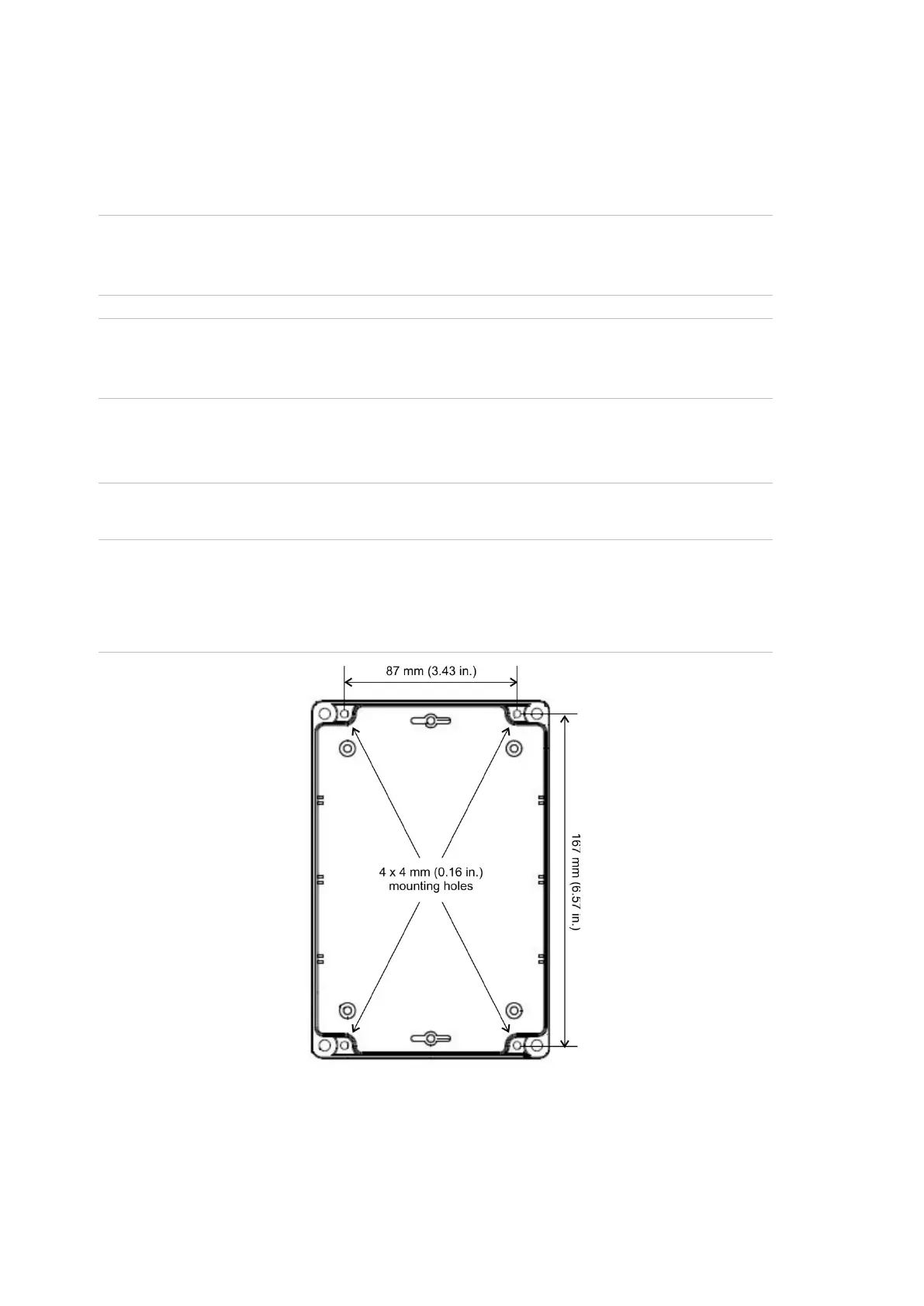
The enclosure has 4 x 4 mm (0.16 in.) mounting holes recessed in each corner
(see Figure 7 below). Remove the front cover to access these.
Figure 7: location of the mounting holes
Mount the enclosure on an even surface (an uneven surface can cause distortion
of the enclosure and internal PCB).
If the anticipated mounting surface is uneven, mount the unit on stand-offs or a
suitable framework to counter the uneven surface.
 Loading...