9
4. Installation Instructions –Supply and Interconnect
Wiring Requirements
• This alarm is designed for installation by a qualified electrician in accordance with local wiring regulations and in
regard to relevant building regulations and codes of practice. In addition, the resistance of the interconnect wiring
shall be a maximum of 10 ohms.
• An appropriate all-pole disconnection device shall be provided as part of the building installation.
• The maximum wire run distance between the first and last unit in a hardwired interconnected system is 300 m.
• When alarms are hardwire interconnected, all interconnected units must be powered from a single circuit.
• This alarm must be powered by a constant 230V AC, 50Hz supply that is not controlled by any form of switch.
• This alarm interconnects with up to 24 other devices (of which 18 can be initiating) including smoke, CO and heat
alarms. (See below). This alarm is not designed to be interconnected with other manufacturer’s products, unless
otherwise specified.
WARNING: The alarm cannot be operated from power derived from a square wave modified square wave or
modified sine wave, inverter. These types of inverters are sometimes used to supply power to the structure in off grid
installations , such as solar or wind derived power sources. These power sources produce high peak voltages that will
damage the alarm.
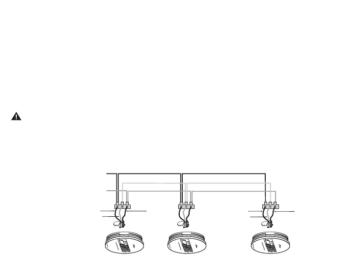
Interconnect Wiring
Line (L)
Neutral (N)
House cabling in compliance with local regulations
Interconnect (I/O)*
Brown
Blue
White* White*
Brown
Blue
NOTE:
Use standard British Standard household cable PVC/PVC 6242Y / 6243Y or equivalent in accordance with local regulations.