Chapter 7: Service and troubleshooting
P/N 3101890-EN • REV 006 • ISS 21JUN18 129
Possible cause
-485 (TB5) network
ive
• The network wiring + and − are reversed
• The VM-NOC card is not seated properly
• The network A and B circuits are crossed
• An improper wire was used
• The communication card is missing
• There is lack of continuity on the network wiring
VM-LCD
control-indicating module
Power LED off
•
The ribbon cable between the LCD and CPU is loose or defective
•
The CPU is defective (replace the entire VM-ELEC electronic
s chassis)
• The LCD is defective (replace the LCD on the VM-ELEC)
• The CPU is not configured in the VM-CU for the VM-LCD
•
There is no power to the panel
VM-NOCF Fiber Network Option module troubleshooting
The VM-NOCF Fiber Network Option Module provides a fiber optic or combination fiber optic and RS-485
communication path for up to eight VM-1 control panels. The module consists of an adapter card and electronics
card.
Separately ordered fiber optic transceivers are installed on the electronics card to provide transmission and
reception capability over the fiber optic cable. The LEDs on the transceivers indicate circuit activity.
Note: If a panel must be powered down for service, connect a backup power source to the 24 VDC terminals
(TB1) on the electronics card to maintain network communication.
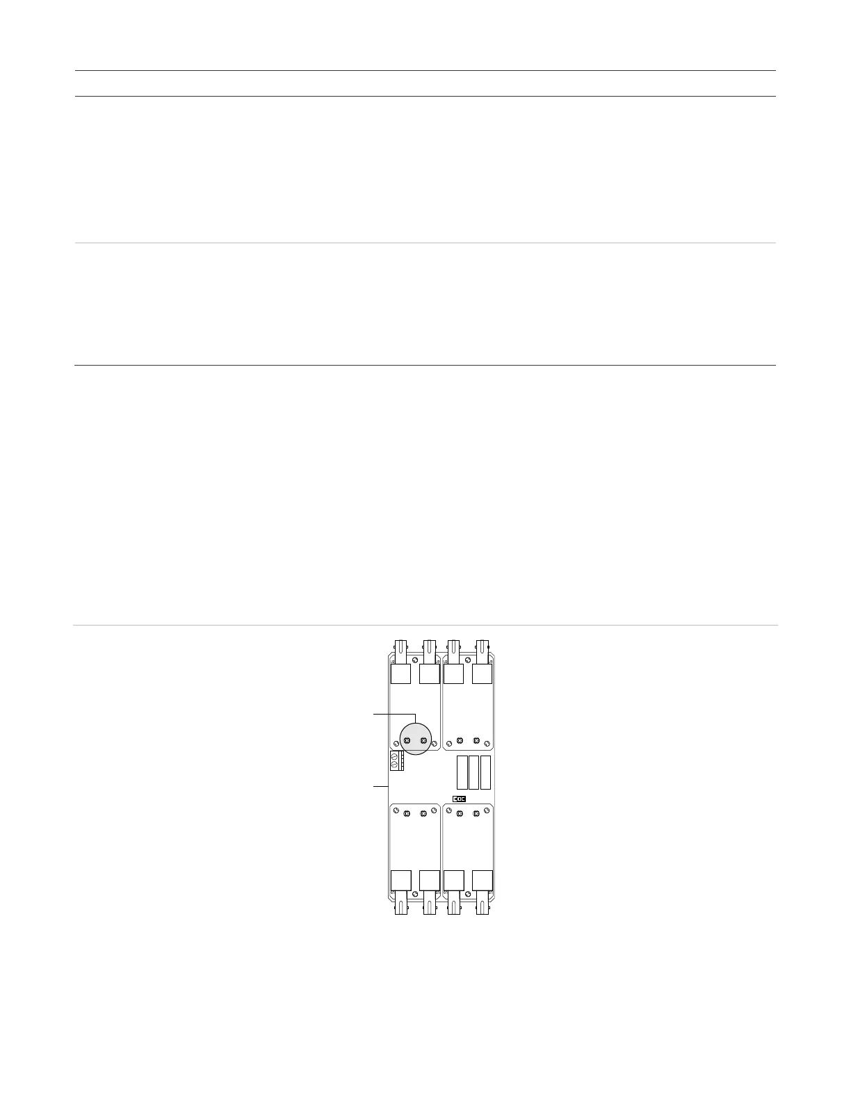
Figure 42: Fiber optic communication LEDs
(1) Tr
ansceiver RX/TX LEDs
(2) Fiber optic module electronics card
TEST
NORMAL
A AUDIO B AUDIO
A DATAB D ATA
RX
TX
RX
TX
RX
TX
RX
TX
TB1
J2
(1)
(2)