Appendix A: System calculations
P/N 3101890-EN • REV 006 • ISS 21JUN18 185
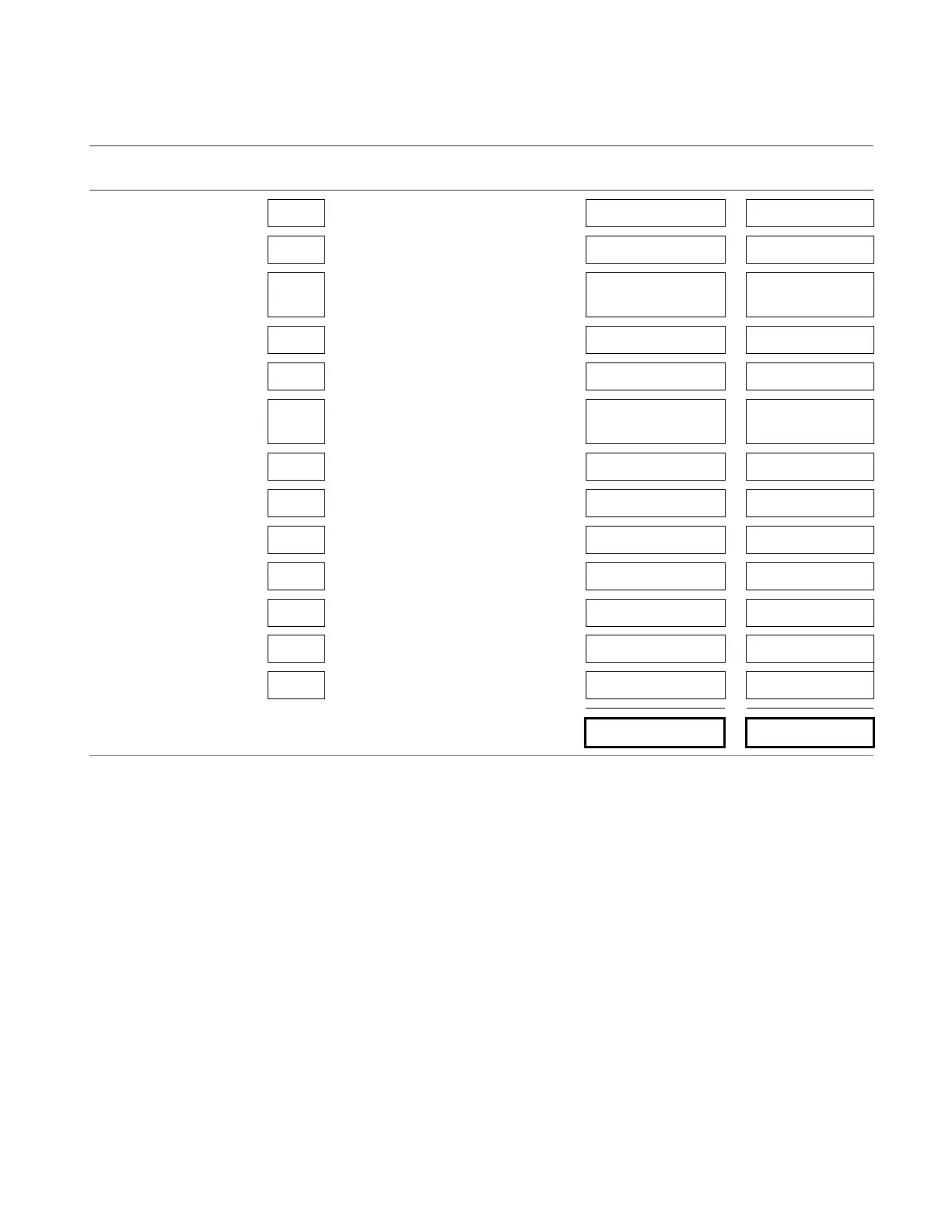
Worksheet A: Control panel current
Instructions: Enter the number of option cards installed in the control panel under Quantity, then calculate the standby and
alarm currents using the values below, and then calculate the total at the bottom.
Devices
Qty
Standby
current (mA)
Alarm
current (mA)
Qty x Standby
current (mA)
Qty x Alarm
current (mA)
Base panel [1] 1 381.0 481.0 381.0 481.0
D12LS-VM [2] 11.0 11.0
VM-SLC or VM-SLC-HC
[3]
120.0 132.0
VM-NOC 98.0 98.0
VM-NOCF [4] 105.0 105.0
VM-ETH1, VM-ETH2, or
VM-ETH3
42.0 54.0
CLA-PS10 2.0 2.0
VM-PMI [5] 23.0 29.0
ACHS 47.0 64.0
VM-MFK [6] 37.0 39.0
VM-DACT 60.0 95.0
VM-SLCXB [7] 144.0 204.0
24DC12 [8] 8.0 750.0
Totals (mA)
[1] Includes the PS10-4B, the VM-CPU, one preinstalled VM-SLC or VM-SLC-HC card with a fully loaded loop circuit, and a
VM-LCD.
[2] Add 2.5 mA for each active LED. Total current does not exceed 58 mA with all LEDs on.
[3] Standby and alarm current values are for one VM-SLC or VM-SLC-HC card with a fully loaded loop circuit. Increase the
device quantity if you add a VM-SLC or VM-SLC-HC card to the VM-CPU or VM-SLCXB. The maximum quantity is two.
[4] Add 71.2 mA for each SMXLO2, 76.8 mA for each SMXHI2, and 20.0 mA for each MMXVR.
[5] Includes EAEC card currents.
[6] Includes telephone controller card and hook-switch card currents.
[7] Standby and alarm current values are for one preinstalled VM-SLC or VM-SLC-HC card with a fully loaded loop circuit. If
you add a second VM-SLC or VM-SLC-HC card to this dual loop module, increase the card device quantity.
[8] Standby and alarm current values are for a 24DC12 without connected devices. Increase the values when you connect a
device. Refer to the device installation sheet for its current values.