Appendix A: System calculations
186 P/N 3101890-EN • REV 006 • ISS 21JUN18
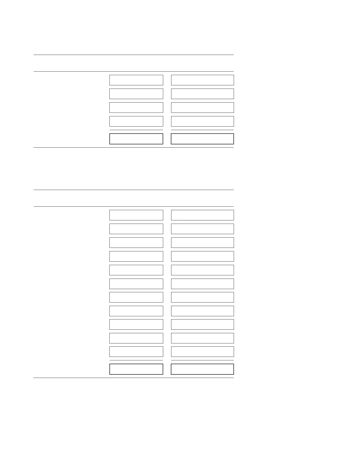
Worksheet B: NAC power current
Instructions: For each NAC/AUX circuit used to provide NAC power, enter the total amount of alarm current required. Use the
DC RMS current values listed on the device’s installation sheet for your calculations.
Devices
Standby
current (mA)
Alarm
current (mA)
NAC/AUX 1
NAC/AUX 2
NAC/AUX 3
NAC/AUX 4
Total (mA)
Worksheet C: AUX power current load
Instructions:
For each NAC/AUX circuit used to provide AUX power, enter the total amount of standby and alarm currents
required by the devices powered by the circuit. Use the standby and alarm currents on the device’s installation sheet for your
calculations.
Devices
Standby
current (mA)
Alarm
current (mA)
NAC/AUX 1
NAC/AUX 2
NAC/AUX 3
NAC/AUX 4
VM-CPU Main Board
RPM module [1]
GSA-REL module [1][2]
SIGA-AA30 amplifier [3]
SIGA-AA50 amplifier [3]
CDR-3 module [1]
IOP3A [1]
Total (mA)
[1} Do not include currents if the module is not installed.
[2] A maximum of ten GSA-REL modules per signaling line circuit can be installed.
[3] Do not include currents if the SIGA-AA30/50 amplifier (installed in an external cabinet) is not power by the VM-1 fire alarm
control panel PS10-4B power supply.