Chapter 5: Installation
80 P/N 3101890-EN • REV 006 • ISS 21JUN18
PS10-4B Power Supply Board
WARNINGS
• Electrocution hazard. To avoid personal injury or death from electrocution, make sure the distribution circuit
providing mains AC is rendered inoperative prior to connecting mains input wiring to the PS10-4B Power
Supply.
• Electrocution hazard. To avoid personal injury or death from electrocution, remove all sources of power and
wait 11 minutes to allow stored energy to discharge before installing or removing equipment.
Caution: Circuit boards are sensitive to electrostatic discharge (ESD). To avoid damage, follow ESD handling
procedures.
One PS10-4B Power Supply Board is required for each control panel. The power supply provides the required
power and related supervisory functions for the control panel as well as filtered, regulated power, and 24 VDC
output for operating notification appliances and ancillary equipment.
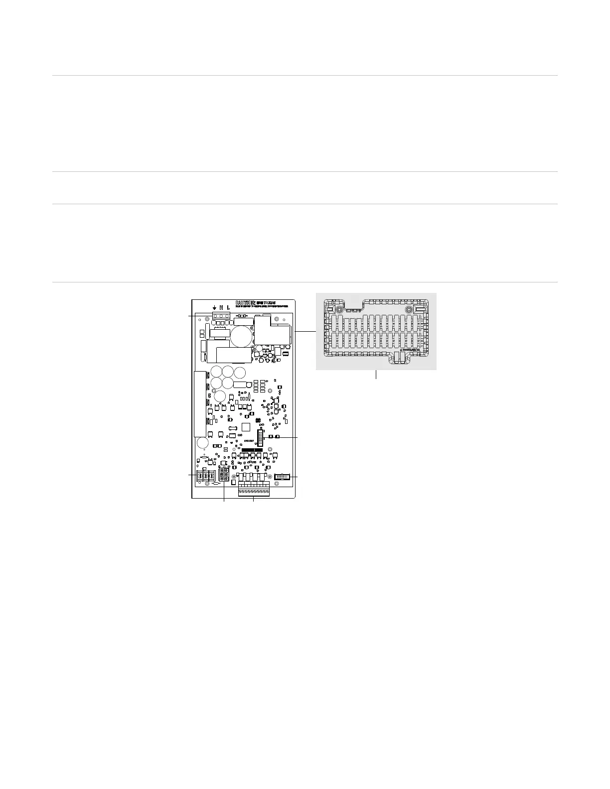
Figure 22: PS10-4B Power Supply Board
(1) Power supply protective cage used in ULC
applications
Data ribbon cable connector
J2 Power supply cable connector
J5 Audio system connector option
TB1 Mains input wiring
TB2 NAC/AUX wiring
On-board terminals and connectors facilitate connection to the VM-CPU, mains input wiring, NAC/AUX wiring,
and battery wiring. The 24 VDC rechargeable battery circuit on the power supply board has the capacity to charge
up to two 65 Ah sealed lead acid batteries. The CAB6B can house up to two 17 Ah batteries. Install batteries
larger than 17 Ah in a separate listed enclosure.
Mains power wiring must be double insulated and connected only to a dedicated 120 V or 230 V mains power
distribution circuit with its own disconnect device. Mains input and battery wiring are supervised and nonpower-
limited. Route nonpower-limited wiring on the left side of the cabinet, as shown in Figure 21 on page 79. See the
PS10-4B Power Supply Board Installation Sheet (P/N 3101774-EN) for connecting power supply field wiring and
for specifications.
TB1
J1
TB3
J5
J3
J1
J4
J5
TB2
TB3
J2
+
-
+
-
+
-
+
-
+
-
NAC AUX 1 NAC AUX 2 NAC AUX 3 NAC AUX 4
N. C.
TB1
TB2J2
(1)