Chapter 5: Installation
P/N 3101890-EN • REV 006 • ISS 21JUN18 79
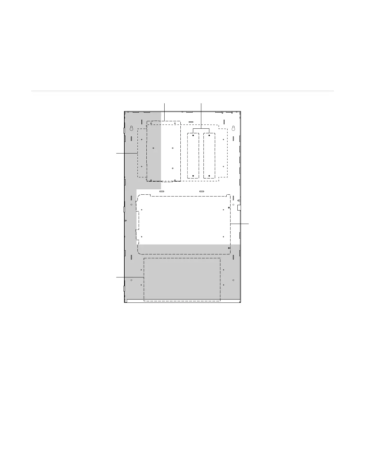
Component installation
The CAB6B backbox holds the power supply, electronics chassis assembly, option cards, standby power supply
batteries, and optional audio subsystem components for the control panel. Figure 21 below shows the footprint
areas for each component. See the installation sheet that came with the component for installation instructions.
Figure 21: CAB6B backbox component footprints
(1) PS10-4B Power Supply Board mounting area
(2) Half-footprint module mounting areas
(3) VM-PMI Paging Microphone Interface mounting area
(4) Standby battery compartment area
(5) VM-ELEC Chassis Electronics Assembly mounting area
Note: Route nonpower-limited wiring on the shaded area of the cabinet and power-limited wiring on the non-
shaded area.