Chapter 5: Installation
88 P/N 3101890-EN • REV 006 • ISS 21JUN18
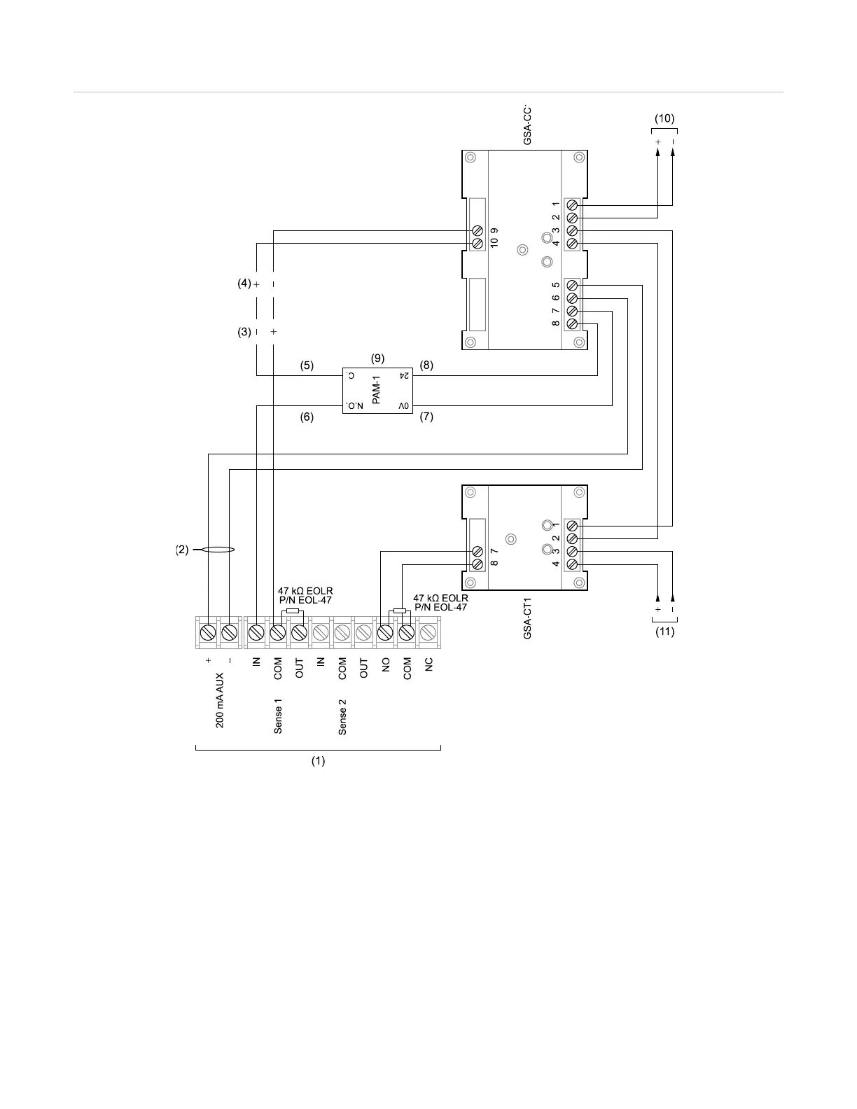
Figure 28: Typical booster power supply wiring
(1) Auxiliary/booster supply
(
2) Not supervised
3) Normal
4) Active
5) Blue
(8) Red
(9) Install a PAM-1 or equivalent listed relay only when required to
supervise the 200 mA AUX circuit wiring
(10) Data Out, Signaling line circuit to next device
(11) Data In, Signaling line circuit from previous device