6-40 Applied Operation PLZ-4W
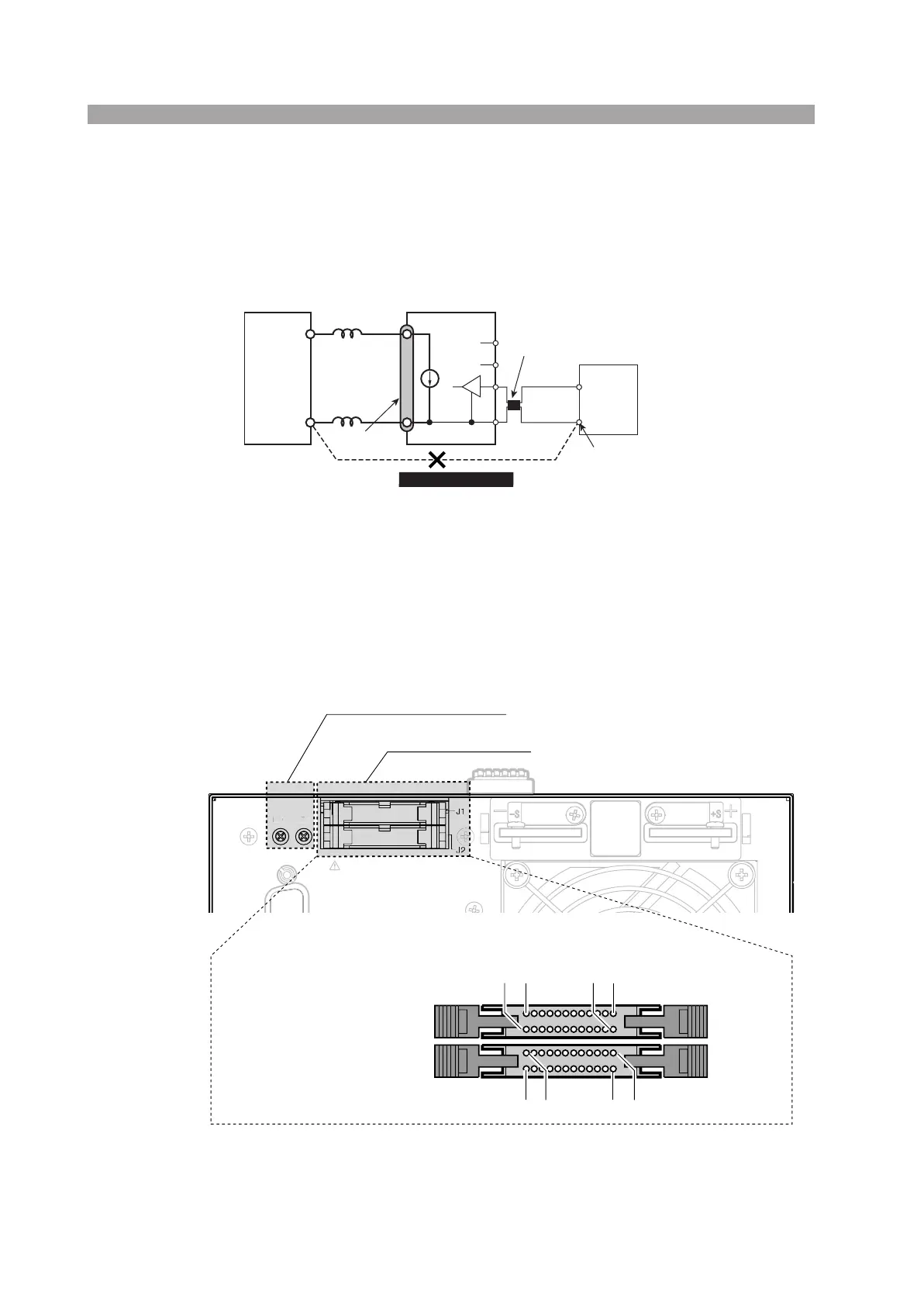
Precaution when operating under high-speed load simulations
When operating under high-speed load simulations, do not connect the common ter-
minal of the external device and the terminal of the EUT which connects to the neg-
ative polarity of load input terminal of the PLZ-4W. Attach the ferrite core on the
connecting wire between the external device and the PLZ-4W.
Fig. 6-22 When operation under high-speed load simulations
6.8.2 J1/J2 connector
The J1 and J2 connectors on the rear panel are of the same shape and the same num-
ber of pins. However, J1 is assigned to external control while J2 is assigned to paral-
lel operation. For details on the pin arrangement, see Table 6-9 or Table 6-10.
Fig. 6-23 Rear panel
L
L
ACOM
+
-
Do not Connect
EUT
Load input
terminals
PLZ-4W
External control terminal
Attach the ferrite core
External
device
Common
terminal
PROTECTIVE GROUNDING CONDUCTOR MUST
BE CONNECTED TO GROUND.
DO NOT REMOVE COVERS, REFER
SERVICING TO QUALIFIED PERSONNEL
TO AVOID ELECTRIC SHOCK, THE POWER CORD
WARNING
OFSFSC
EXT CONT
C1 DT0 C0 E1
DC INPUT
165W
1.5
-
150V
0
-
33A
External control connector
Pin number of the external
control connector
J1
J2
1
2
19
20
121920
External control
Full scale and offset adjustment
F
XT
N
 Loading...