PLZ-4W Applied Operation 6-53
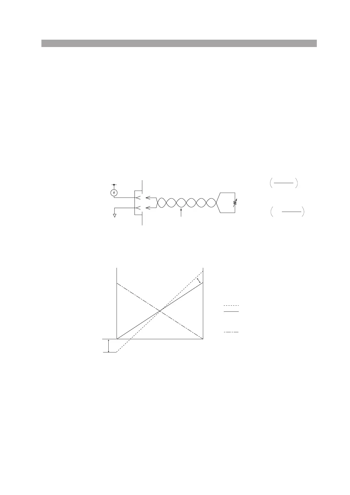
(2) External resistance control
Connecting an external resistance in the range of 0 Ω to 10 kΩ to the PLZ-4W pro-
duces a wattage that is proportional or inversely proportional to the change.
Proportional control
The wattage corresponding to the external resistance of 0 Ω is 0 W; the wattage cor-
responding to the external resistance of 10 kΩ is 100 % of the specified range.
Inverse proportional control
The wattage corresponding to the external resistance of 10 kΩ is 0 W; the wattage
corresponding to the external resistance of 0 Ω is 100 % of the specified range.
Connected pins: J1-1 (signal), J1-3 (common)
Fig. 6-34 Equivalent circuit
Fig. 6-35 Control the wattage using external resistance
■ The setup procedure is the same as with CC mode.
See page 6-45 “Setup procedure for external voltage control”.
1
J1
Rin
Po ≈ Pm
Po: Input power
Pm: Rated power
Rin: External variable resistor
0 ≤ Rin ≤ approx. 10 kΩ
Rin(kΩ)
10
Rin(kΩ)
10
3
Proportional control
Inverse proportional control
1 mA
MAX12 V
A COM
EXT R/V CONT
Po ≈ Pm
1–
Twist
Pm
Pm
0 W
External resistor Rin
: Rated power
: Input power (before adjustment)
: Input power (after adjustment)
: Input power (after adjustment)
Proportional control
Inverse proportional control
0 Ω 10 kΩ
Input power Po
Offset
adjustment
Full scale adjustment
 Loading...