17
This instruction manual is for the installation of the
Hydraulic Box Auger. This unit can be installed on all
Killbros boxes.
CAUTION! BE SURE TO FOLLOW ALL
INSTRUCTIONS CLOSELY. ALWAYS TAKE THE
GIVEN PRECAUTIONS TO PREVENT BODILY
INJURY.
CAUTION! BEFORE INSTALLATION CAN
BEGIN, BE SURE THAT THE RUNNING GEAR IS
SECURELY BLOCKED TO PREVENT MOVEMENT.
FAILURE TO DO SO COULD RESULT IN DAMAGE
TO AUGER OR CAUSE BODILY INJURY.
1. Remove existing chute and hardware from door
angles on gravity box.
NOTE: When installing hardware, do not tighten until
instructed to do so. This will allow for easier
installation of components.
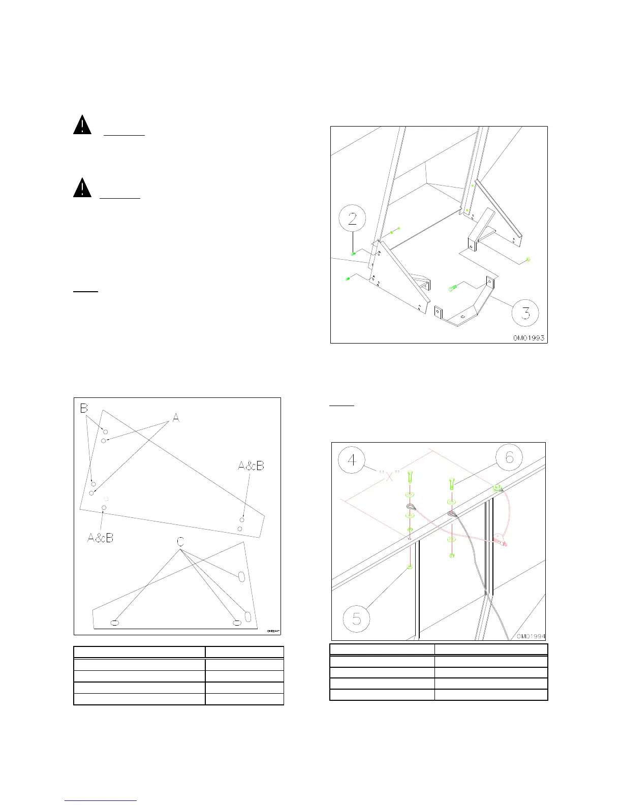
2. Locate pan brackets onto door angles. Use the
following diagram (Figure 3-1) and secure using two
5/16 x 1 1/4” capscrews, two lockwashers and two
hex nuts per bracket (Figure 3-2). *Note on “55”
Series, bolt side pan brackets to chute brackets using
1/2” x 1 1/4” bolts.
Killbros Box Hole
#350
A
#385
B
#390
B
3. Position swing bracket between the mounting
arms. The bracket base where the auger will
mount, should have the smaller length between
brakes pointing away from the box (Refer to
Figure 3-2). Secure using two 1/2 x 1 1/4”
capscrews and locknuts.
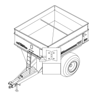
4. Drill two 3/8” holes in the lips of the gravity box
where indicated in Figure 3-3. These holes will
secure the swivel cable.
NOTE: Be sure to center swivel cable on box lip as
shown.
Killbros Box "X" DIMENSION
#350 32"
#385 36"
#390 36"
5. Mount swivel cable using two 3/8 x 1 1/2”
capscrews, four large washers, a hex nut, and a
flange nut per eye as shown. Locate the eye
FIG. 3-1
FIG. 3-2
FIG. 3-3