23
ELECTRONIC VALVE ASSEMBLY
These instructions are for the installation of the
Electronic Control for the Killbros Hydraulic Box
Auger. This accessory will allow for convenient on /
off control of the auger.
To install this unit, a 12 Volt D.C. electrical source
must be available. DO NOT install into any electrical
system that does not meet these specifications.
Failure to abide will result in damage to components.
CAUTION! BE SURE TO FOLLOW ALL
INSTRUCTIONS CLOSELY. ALWAYS TAKE THE
GIVEN PRECAUTIONS TO PREVENT BODILY
INJURY.
CAUTION! BEFORE INSTALLATION CAN
BEGIN, BE SURE THAT THE AUGER AND
IMPLEMENT IT IS INSTALLED ON IS SECURELY
BLOCKED TO PREVENT MOVEMENT. THIS WILL
PROVIDE A SAFE WORKING ENVIRONMENT
WHILE INSTALLING THE ELECTRONIC CONTROL.
WARNING! BEFORE DISCONNECTING
AUGER HYDRAULICS, BE SURE THAT ALL
PRESSURE IS RELIEVED. FAILURE TO DO SO
COULD RESULT IN INJECTION OF HYDRAULIC
FLUID INTO SKIN OR EYES. THIS COULD RESULT
IN INFECTION OR IN SOME CASES DEATH.
NOTE: Be sure to disconnect hydraulics while
working in an environment clean of dirt and debris. If
dirt should enter into the system, flush system.
Failure to remove dirt could result in premature motor
failure or damage to system supply.
1. Relieve hydraulic pressure and disconnect valve
from hydraulic lines and from motor by loosening the
four bolts.
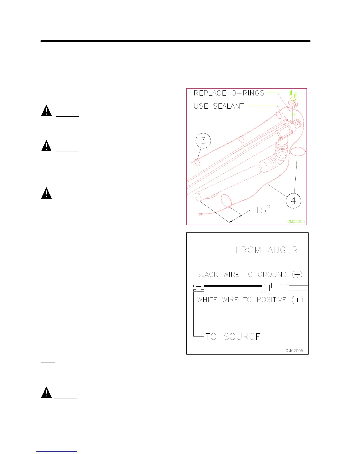
2. Apply an SAE approved sealant and connect new
fittings to hydraulic lines and then to valve. Position
valve on motor with new “O” rings and secure using
the four bolts and lock washers that held the previous
valve (Figure 3-14).
3. Position the electrical lines down the length of the
auger tube along the hydraulic lines. Secure the
cable to the hydraulic line using the seven 6” cable
ties provided (Figure 3-14).
NOTE: Be sure cable is taught along auger tube. A
loose or drooping wire will tend to catch and be torn.
4. Run the switch down the spout as shown. Secure
using two 28” cable ties. Position bottom tie strap
approximately 15 inches from bottom of spout to
allow for easy access to switch.
NOTE: Depending on the length of the spout, excess
wire may need to be looped and securely tied to
auger.
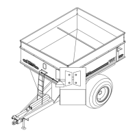
CAUTION! BE SURE TO CONNECT WHITE
WIRE (+) TO POSITIVE 12 VOLT D.C. POWER
SUPPLY. FAILURE TO DO SO COULD RESULT IN
DAMAGE TO VALVE.
FIG. 3-14
FIG. 3-15