21
WARNING! BE SURE ALL PRESSURE IS
REMOVED FROM HYDRAULIC SYSTEM WHEN
DISCONNECTING OF CONNECTING HOSES OR
FITTINGS. HYDRAULIC SYSTEMS CONTAIN HIGH
PRESSURE FLUID WHICH CAN EASILY
PENETRATE SKIN. THIS COULD RESULT IN
SEVERE INFECTION OR EVEN DEATH.
IMPORTANT! WHEN CHECKING FOR
HYDRAULIC LEAKS, PLACE CARDBOARD BELOW
THE SUSPECTED AREA. NEVER USE HANDS OR
FINGERS TO DETECT FOR LEAKS, INJECTION OF
HYDRAULIC FLUID INTO SKIN CAN OCCUR.
21. Connect hydraulic hoses to lines on the auger.
Be sure to prevent leaks (Figure 3-10).
22. Route hoses to front of the gravity box and install
hose bracket. Drill a 3/8 inch hole near the
bottom of the box as shown. Be sure to mount
towards the front of the box. Secure bracket
using a 5/16 x 3/4” capscrew and locknut (Figure
3-10).
23. Mount hose coupler bracket to front of gravity
box. Position where desired and drill a 3/8 inch
hole. Secure using 5/16 x 1 1/4” capscrew and
locknut. Mount hoses to bracket and secure
using sealant.
NOTE: Hoses from bracket to hydraulic supply are
not provided. Use a hose diameter of at least 1/2
inch.
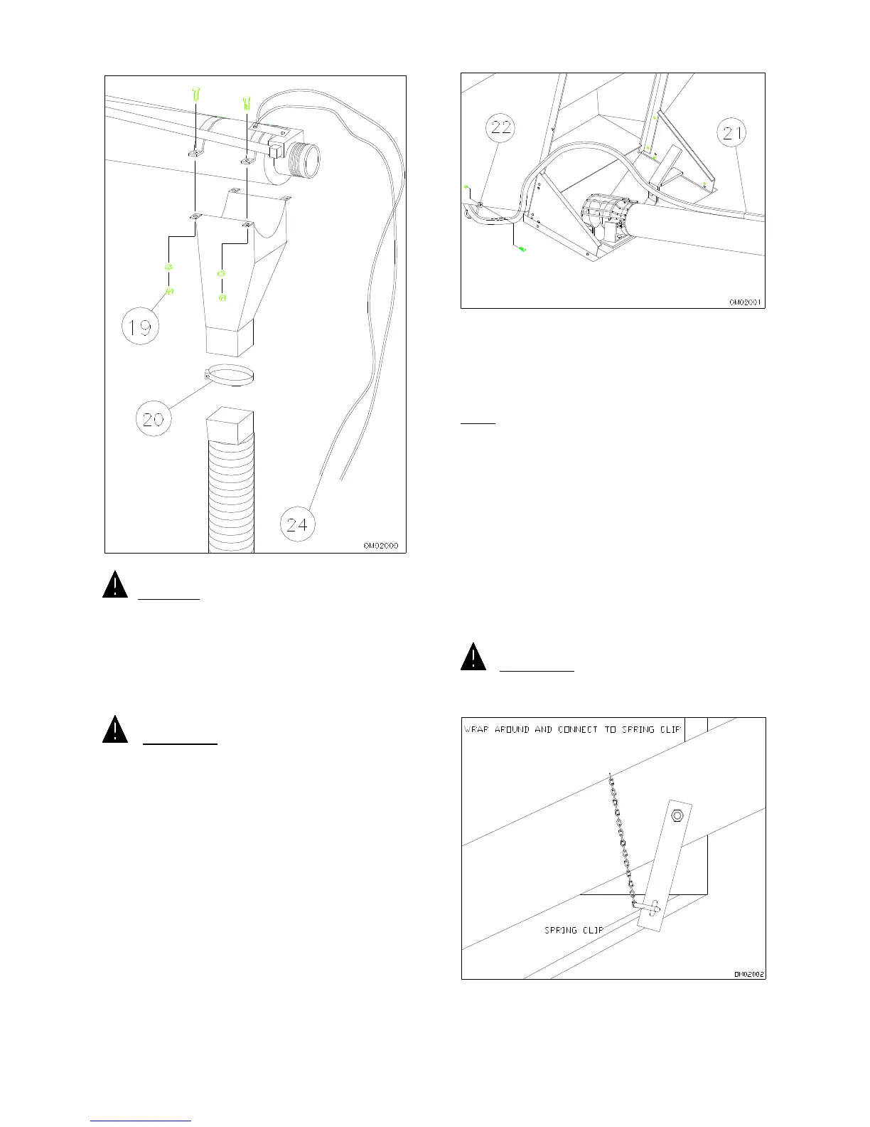
24. Connect rope to valve handle by threading
through eye, tying in middle and dangling both
ends (Figure 3-9).
25. Maneuver auger around and into transport
bracket to check for any interference. Adjust
accordingly.
26. Connect to hydraulic supply and operate auger.
Be sure of correct auger rotation. Switch hose
connections if required to reverse rotation.
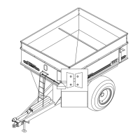
IMPORTANT! FOR SAFE TRANSPORT,
ALWAYS WRAP CHAIN AROUND AUGER IN THE
TRANSPORT BRACKET TO PREVENT AUGER
FROM FALLING OUT (FIGURE 3-11).
FIG. 3-10
FIG. 3-11
FIG. 3-9