20
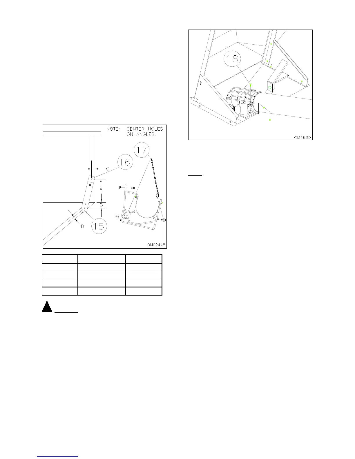
15. Position transport bracket as indicated in Figure
3-7. Mark the bottom hole 4 inches from the end
of the box while centering the hole on the angle.
Drill a 3/8 inch hole at this location.
16. Attach transport bracket by inserting a 3/8 x 1
1/4” capscrew, large flat washer, and locknut.
Rotate bracket around until it is centered on the
vertical angle. Mark and drill the hole. Install
hardware and tighten (Figure 3-7).
17. Attach chain to bracket using 5/16” bolt, washer
and locknut to inside of bracket. Attach eyebolt
with two nuts, where shown allowing clip to
secure chain around auger. (Figure 3-7).
"A"
8 3/4 3
1 3/4 7 3/4
1 1/4 23
1 1/4 1 1/2
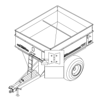
CAUTION! FLIGHTING GUARD SHOULD NOT
BE REMOVED AT ANY TIME DURING OPERATION
OF AUGER. FAILURE TO DO SO COULD RESULT
IN BODY PARTS ENTERING THE FLIGHTING PATH
AND SEVERE BODILY INJURY WILL RESULT.
18. Install flighting guard to bottom of auger by
positioning as shown. Secure using a strap and
two 1/4 x 1” capscrews, two lock washers and
two hex nuts (Figure 3-8).
NOTE: Before tightening guard, maneuver auger
around to check for interference. Adjust if necessary
and tighten.
19. Secure fertilizer spout to auger by centering over
hole in tube and installing two straps and four 1/4
x 1 1/2” capscrews, lock washers, and hex nuts
(Figure 3-9).
20. Connect the rubber spout to the fertilizer spout
by sliding over fertilizer spout and installing the
tube clamp (Figure 3-9).
FIG. 3-7
Fig. 3-8