ADJUSTING SPEED SELECTOR DIAL
The machine speed can be adjusted between
500 and 3,000 strokes per minute by turning
the speed selector dial (A) Fig.4. The dial is
marked 1 (lowest speed) to 6 (full speed). In
general, higher speeds will allow you to cut
workpieces faster but the service life of the
blade will be reduced.
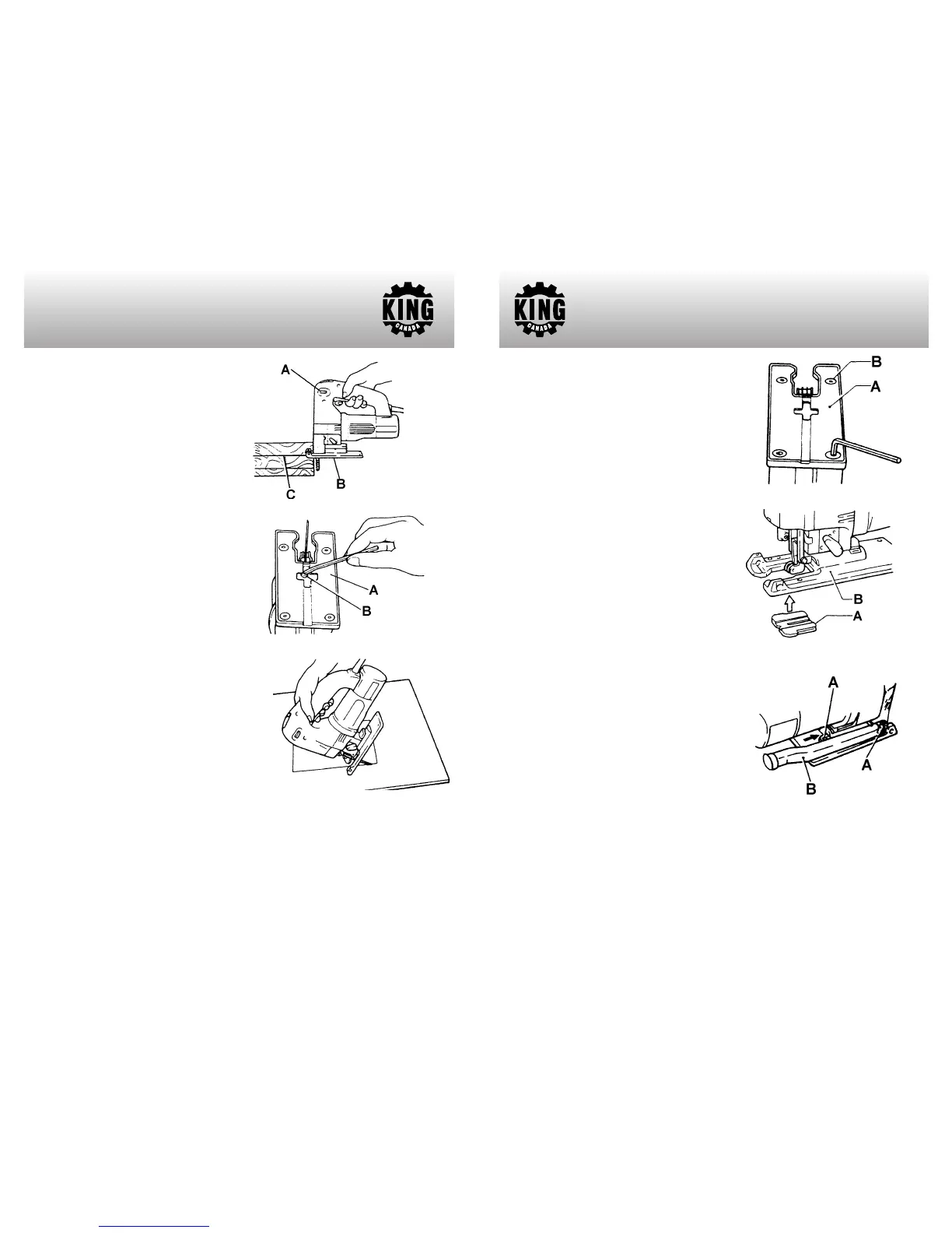
CUTTING OPERATION
Rest the base (B) Fig.4 flat on the workpiece
and gently move the machine forward along
the previously marked cutting line (C). When
cutting curves, advance the machine very
slowly.
BEVEL CUTTING
With the base (A) Fig.5 tilted, you can make
bevel cuts at any angle between 0˚ and 45˚
(left or right). Loosen the cap screw (B) on the
bottom of the machine using the hex. key.
Move the base so that the cap screw is
positioned in the center of the cross-shaped
slot in the base. Tilt the base until the desired
bevel angle is obtained. The edge of the
motor housing indicates the bevel angle.
Retighten the cap screw to secure the base.
FLUSH CUTTING
Loosen the cap screw on the bottom of the
machine and move the base all the way back.
Then tighten the bolt to secure the base.
ASSEMBLY & OPERATION
Figure 4
Figure 5
Figure 6
CUTOUTS
Cutouts can be made with either methods A or B.
A) Boring a starting hole: for internal cutouts without a lead-in cut from an edge, pre-drill a
starting hole more than 12mm in diameter. Insert the blade into this hole to start your cut.
B) Plunge cutting: You do not need to bore a starting or make a lead-in cut if you
carefully do as follows: Tilt the machine up on the front edge of the base Fig.6, with the
blade point positioned just above the workpiece surface.
Apply pressure to the machine
so that the front edge of the base will not move when you switch on the machine and
gently lower the back end of the machine slowly. As the blade pierces the workpiece,
slowly lower the base of the machine down onto the workpiece surface. Complete the
cut in the normal manner.
METAL CUTTING
Always use a suitable coolant (cutting oil)
when cutting metal. Failure to do so will cause
a significant blade wear. The underside of the
workpiece can be greased instead of using a
coolant.
PLASTIC BASE INSERT
Use the plastic base insert (A) Fig.7 when
cutting decorative veneers, plastics, etc. It
protects sensitive surfaces from damage. To
replace the base insert, remove the four
screws (B).
ANTI-SPLINTERING DEVICE
For splinter-free cuts, the anti-splintering
device (A) Fig.8 can be used. Fit into the base
from below as shown.
DUST CHUTE
The supplied dust chute (B) Fig.9 can be
installed on either the right or left side of the
base, depending on practicality. To install the
dust chute, slide the dust chute pins into the
top of the base (A) as shown.
Important note: The front plastic guard must
be removed in order to install the dust chute
to the base (right or left side).
ASSEMBLY & OPERATION
Figure 7
Figure 8
Figure 9
PARTS DIAGRAM & PARTS LISTS
Refer to the Parts section of the King Canada web site for the most updated parts
diagram and parts list.
 Loading...