ASSEMBLY &
OPERATION CONTROLS
ASSEMBLY OFTHEAIRCOMPRESSOR
Your compressor comes almost completely assembled.
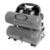
1) Install the muffler (A) Fig.3 to the cylinder cover (B) by screwing it into place as shown.
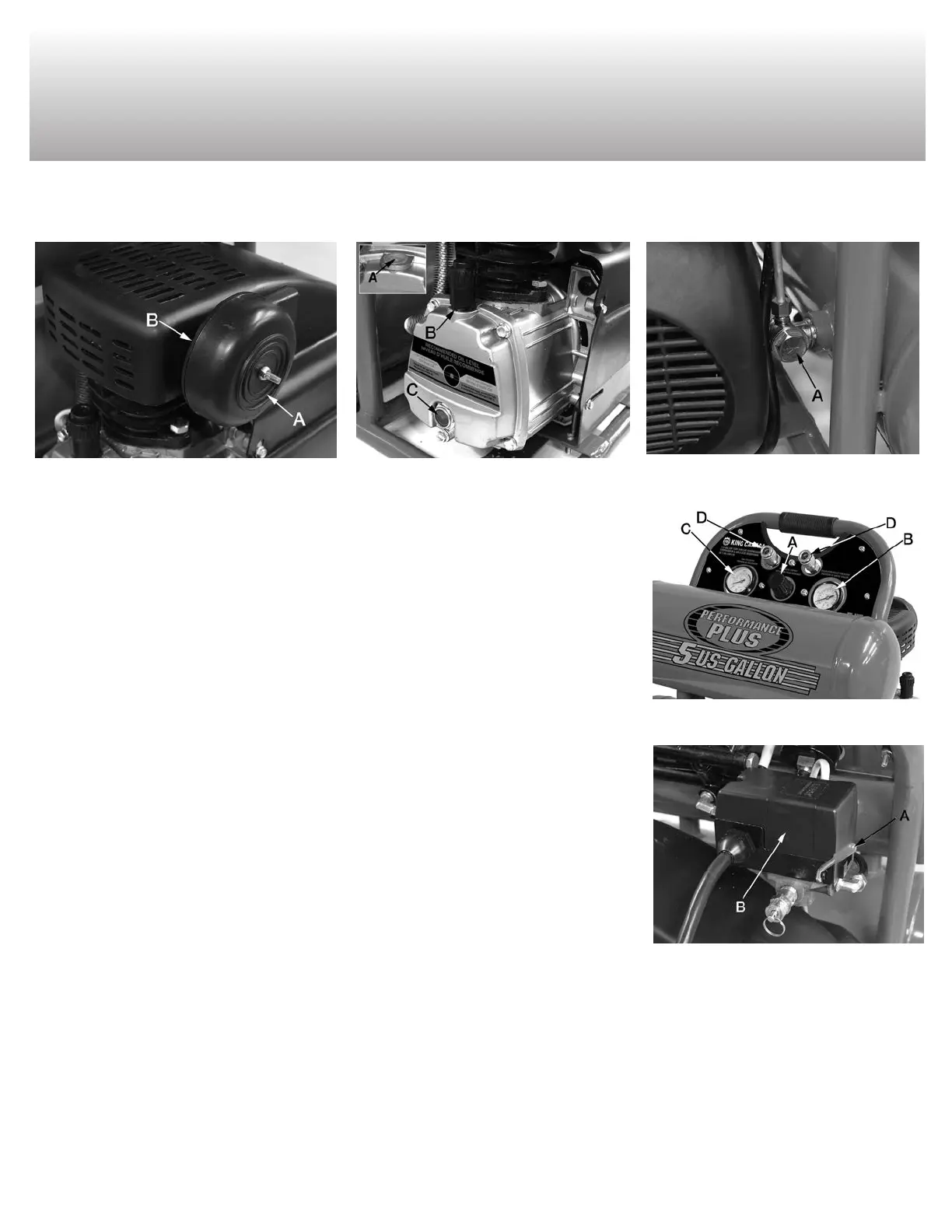
2) Remove the plastic cap (A) Fig.4 and replace it with the oil breather cap (B) by screwing it into place as shown.
LOCATIONTO USE THEAIRCOMPRESSOR
Operate the air compressor in a dry, clean, cool, well ventilated area. The air compressor pump and
case are designed to allow for proper cooling. Clean or blow off dust or dirt that collects on the air
compressor. A clean air compressor runs cooler and provides longer service. The ventilation openings
on your air compressor are necessary to maintain proper operating temperature. Do not place rags
or other containers on or near these openings.
ADDITIONALREGULATORSANDCONTROLS
Since the air tank pressure is usually greater than that which is needed, a regulator is employed to
control the air pressure ahead of any individual driven device. Separate air transformers which com-
bine the function of air regulation, moisture and dirt removal should be used where applicable.
OPERATIONCONTROLS
AIR COMPRESSOR PUMP. To compress air, the piston moves up and down in the cylinder. On the
downstroke, air is drawn in through the intake valves. The exhaust valves remain closed. On the up-
stroke of the piston, air is compressed. The intake valves close and compressed air is forced out
through the exhaust valves.
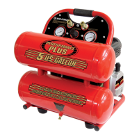
CHECKVALVE (A) FIG.5. When the air compressor is operating, the check valve is “open”, allowing
compressed air to enter the air tanks. When the air compressor reaches “Cut-Out” pressure, the
check valve “closes”, allowing air pressure to remain inside the air tanks.
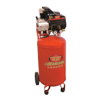
REGULATOR (A) FIG.6. The air pressure coming from the air tanks is controlled by the regulator.
Turn the regulator knob clockwise to increase pressure and counterclockwise to decrease pressure.
To avoid minor readjustment after making a change in the pressure setting, always approach the de-
sired pressure from a lower pressure. When reducing from a higher to a lower setting, first reduce
the pressure less than that desired, then bring it up to the desired pressure. Depending on the air re-
quirements of each particular accessory, the outlet regulated air pressure may have to be adjusted
while operating the accessory.
OUTLET PRESSURE GAUGE (B) FIG.6. The outlet pressure gauge indicates the air pressure available at the outlet side of the regulator. The
pressure is controlled by the regulator and is always less than or equal to the tank pressure.
TANK PRESSURE GAUGE (C) FIG. 6. The tank pressure gauge indicates the reserve air pressure in the tank.
ON/AUTO-OFF SWITCH (A) FIG.7. Turn this switch ONto provide power to the automatic pressure switch and OFF to remove power at the end
of each use.
PRESSURESWITCH (B) FIG.7. The pressure switch automatically starts the motor when the tank pressure drops below the factory set “Cut-In”
pressure. It also stops the motor when the air tank pressure reaches the factory set “Cut-Out” pressure.
FIGURE 3
FIGURE 4
FIGURE 5
FIGURE 6
FIGURE 7