COOLING SYSTEM. This compressor contains an advanced design cooling system. The cooling
system is working when air is being expelled.
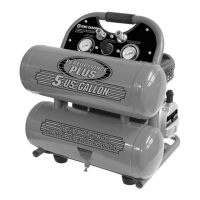
SAFETY VALVE (A) FIG. 8. If the pressure switch does not shut off the air compressor at its cutout
pressure setting, the safety valve will protect against high pressure by “popping out” at its factory set
pressure (slightly higher than the pressure switch cut-out setting).
WARNING!: If the safety valve does not work properly, over pressurization may occur, causing air
tank rupture or an explosion. Daily pull the ring on the safety valve to make sure that the safety valve
operates freely. If the valve is stuck or does not operate smoothly, it must be replaced with the same
type of valve.
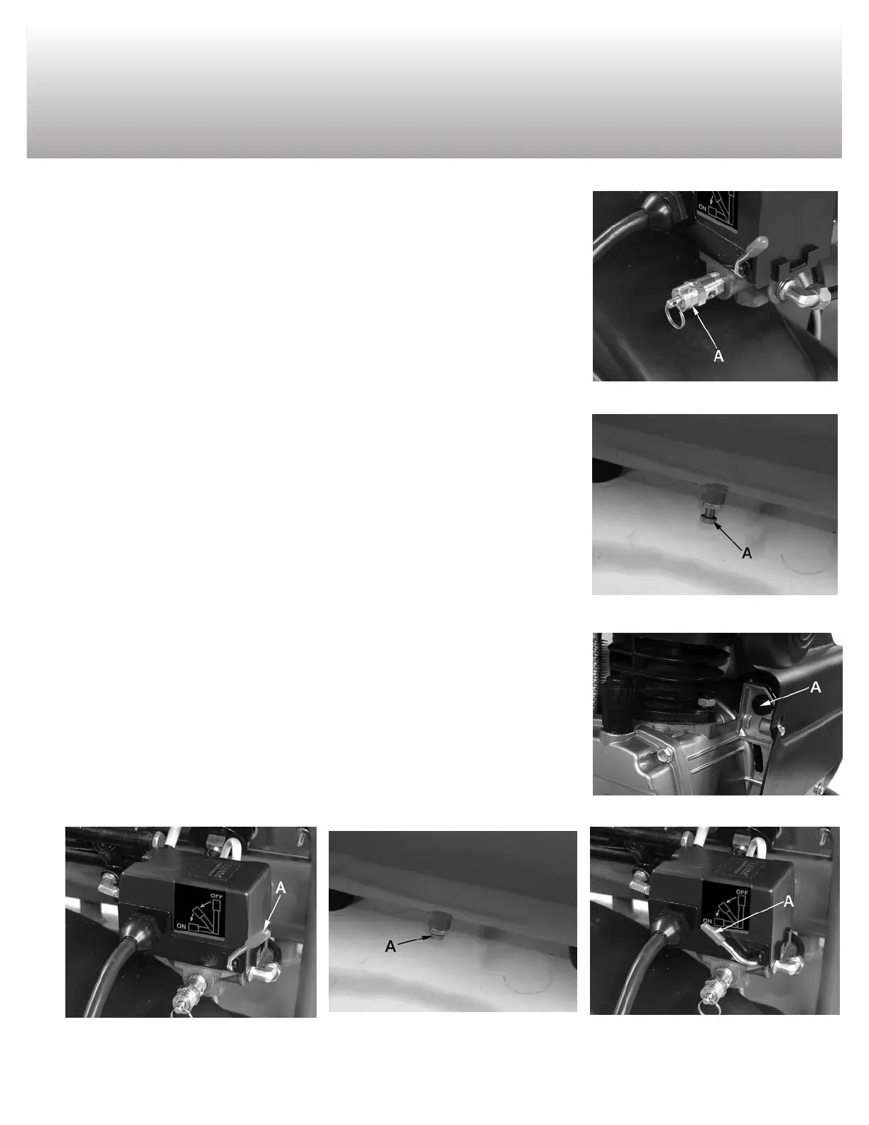
DRAIN VALVE (A) FIG. 9. The drain valve is located at the base of the air tank and is used to drain
condensation at the end of each use.
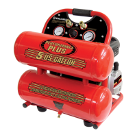
MOTOR THERMAL OVERLOAD PROTECTOR (RESET (A) FIG.10). The electric motor has an au-
tomatic thermal overload protector. If the motor overheats for any reason, the thermal overload pro-
tector will shut off the motor. The motor must be allowed to cool before restarting. Wait for motor to
cool down, once motor is cool, press the reset button and restart.
*IMPORTANT BREAK-INPROCEDURES*
NOTE: MAKE SURE ALL ASSEMBLY INSTRUCTIONS ABOVE HAVE BEEN FOLLOWED BE-
FORE DOING THE FOLLOWING “BREAK-IN PROCEDURES” (MUFFLER AND OIL BREATHER
CAP. SERIOUS DAMAGE MAY RESULT IF THE FOLLOWING BREAK-IN INSTRUCTIONS ARE
NOT CLOSELY FOLLOWED. THESE PROCEDURES ARE REQUIRED BEFORE THE AIR COM-
PRESSOR IS PUT INTO SERVICE, AFTER REPLACING THE CHECK VALVE, AND WHEN THE
PISTON OR THE CYLINDER SLEEVE ARE REPLACED.
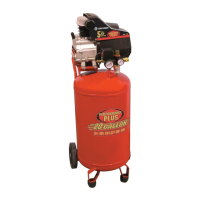
1) Set the pressure switch lever (A) Fig.11 to the “OFF” position.
2) Plug the power cord into grounded 120V branch circuit receptacle.
3) Open the drain valve (A) Fig.12, turn it counterclockwise as shown, this will prevent air pressure
build-up in the tank.
4) Move the pressure switch lever (A) Fig.13 to “ON/AUTO”. The compressor will start.
5) Run the compressor for 15 minutes. Make sure the drain valve is open and there is no tank
pressure build-up (tank pressure gauge at zero).
6) After 15 minutes, close the drain valve by turning it clockwise. The air receiver will fill tank to cut-
out pressure and the motor then will stop. The air compressor is now ready for use.
FIGURE 8
OPERATION CONTROLS
& BREAK-IN PROCEDURES
FIGURE 9
FIGURE 11
FIGURE 12
FIGURE 13
FIGURE 10