_________________________________________________________________________________________
Page
5
of
11
Ver 1.7 File No.:RTU5034103
A Professional GSM 3G M2M products manufacturer
and automation solution provider, since 2005.
www.4G-RTU.com Support@GSM-Gate-Opener.com
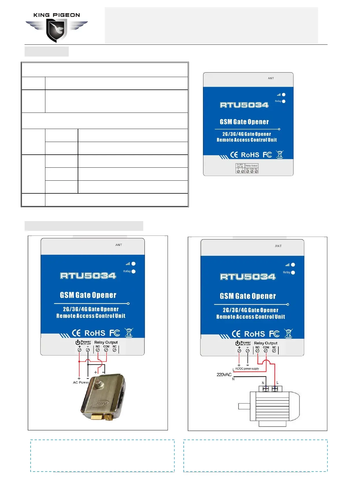
3. Diagram
4. Typical wiring connection:
ON: Relay closed(ON). OFF: Relay open(OFF)
Flash per 0.8 second(quickly): registering to cellular network.
Flash per 2 seconds: Normal status.
OFF: can’t connect to SIM card or unregistered to the cellular network
Power supply input, Positive wire(Red).
Power supply input, Negative wire(Black).
2. RTU5034 for remote switch:
The pump switched ON/OFF by phone call. Pump power up by the
grid/electricity, and RTU5034 power up by AC/DC adaptor.
1. RTU5034 for Gate opener:
Power up the RTU5034 and electronic lock by same DC source, the
lock switched ON/OFF by phone call.
 Loading...