17
FPPBC25-6
Getting Started . . .
Before you start
2.
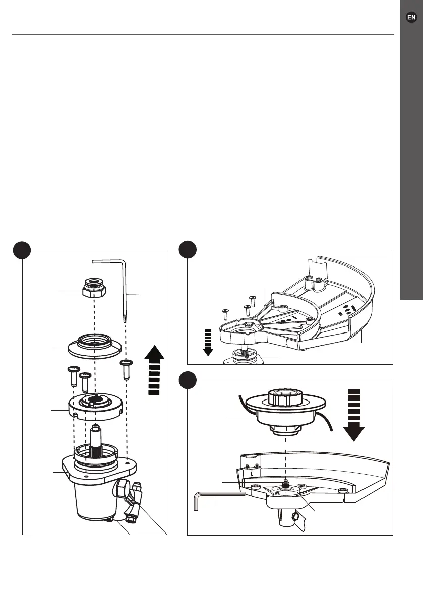
Loosen the three pre-assembled screws on the gear head (18), using the
multi-tool II (34) (Fig. 3).
3. With one hand holding the backing ange (23) and the locking ange (25), turn the
securing nut (26) clockwise to loosen it.
4. Remove the securing nut (26), the locking ange (25) and the backing ange (23)
from the gear head (18).
5.
Attach the cutting-attachment guard (22) with the trimming guard (27) to the gear
head (18). Secure the guard with the removed three screws (Fig. 4).
6. Put the backing ange (23) onto the spindle (30) (Fig. 5).
7. Rotate the backing ange (23) until one of its grooves is aligned with one of those
on the spindle (30).
8. Insert the hex key (36) into one of the grooves to lock the rotation of the spindle.
9. Screw the trimmer head (28) onto the spindle anti-clockwise securely.
10. Make sure the trimmer head (28) is rmly tightened and remove the hex key (36).
5
28
23
30
36
18
23
25
34
26
3
22
27
18
4
 Loading...