EasyManua.ls Logo

Kingfisher PLUS+ - Al-10 Wiring Diagram

Kingfisher PLUS+
26 pages
Print Icon
To Next Page IconTo Next Page
To Previous Page IconTo Previous Page
Loading...
Kingfisher PLUS+ Installation Manual 2.6
www.cse-semaphore.com/mykingfisher
Page 12
8.3 AI-10 Wiring Diagram
1
2
3
4
5
6
7
8
9
10
11
12
13
14
15
16
17
18
19
20
CH 3-
CH 1+
CH 2-
CH 1-
CH 2+
Wiring Examples
CH 3+
CH 4-
CH 4+
0 V
+24 V Output
CH 7-
CH 5+
CH 6-
CH 5-
CH 6+
CH 7+
CH 8-
CH 8+
0 V
+24 V Output
CH x +
+24 V
Output
2-wire transmitter *
(powered by module)
CH x -
LOOP
0 V
+
-
Analog
Input
CH x -
CH x +
+24 V
Output
3-wire transmitter *
(powered by module)
0 V
PWR
+
-
Analog
Input
4-wire transmitter
(powered by module) CH x -
CH x +
+24 V
Output
0 V
PWR
+
-
Analog
Input
4-wire transmitter
(powered externally)
+
-
CH x +
CH x -
Analog
Input
PWR
POWER
SUPPLY
+
-
3-wire transmitter
(powered externally)
+
-
CH x +
CH x -
Analog
Input
PWR
POWER
SUPPLY
+
-
CH x +
2-wire transmitter
(powered externally)
CH x -
+
-
Analog
Input
POWER
SUPPLY
+
-
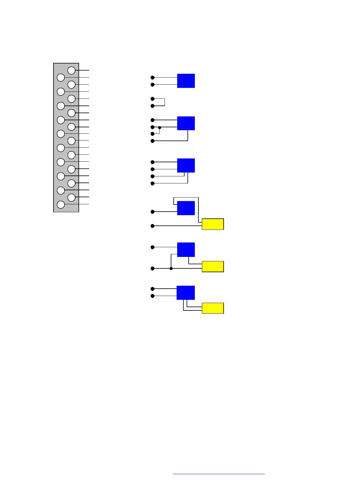
* When using the +24V output to power a transmitter, the negative input terminal of the analog input channel (2, 4,
6, 8, 12, 14, 16 or 18) must be wired to the OV terminal (10 or 20). This will complete the current loop due to
electrical isolation between the input channel and the module +24V supply.
Note: Any channels sharing the same power source (e.g. +24V from module or a field power supply) are no
longer isolated from one other.