8
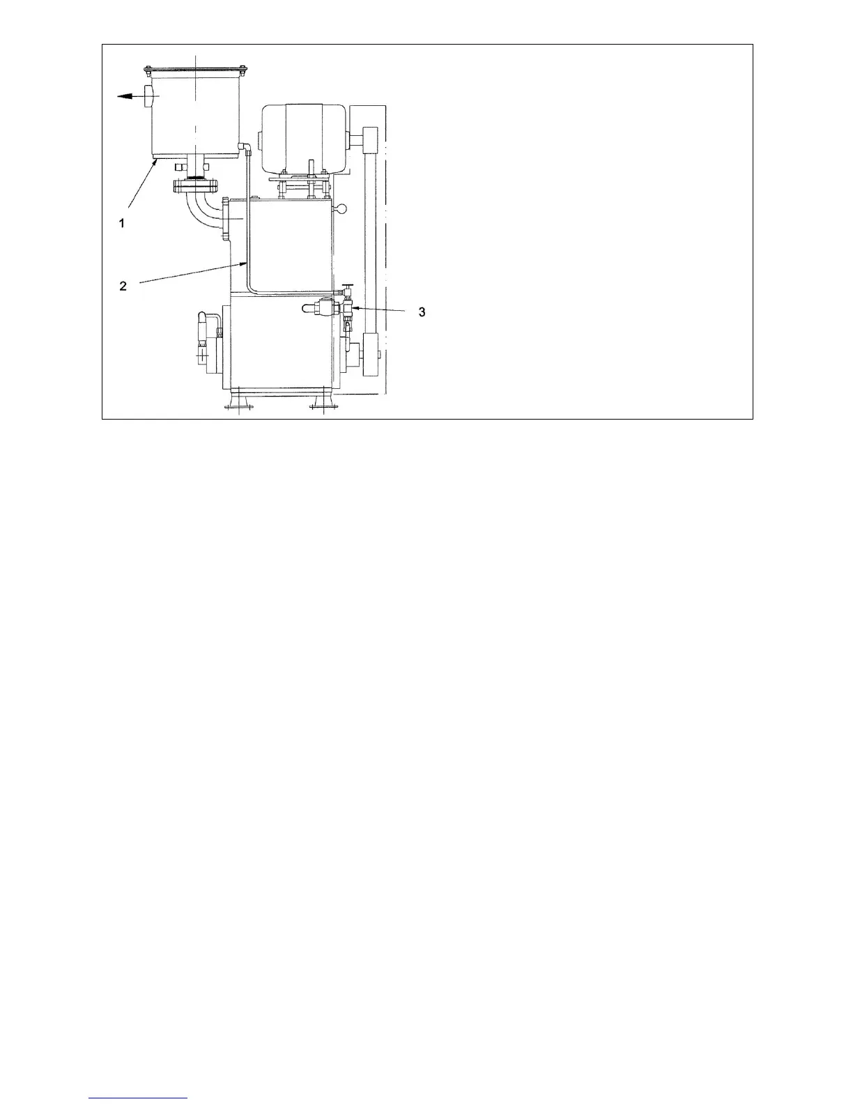
Figure 3. Oil Return to the Gas Ballast Valve
Suction Manifolding
Inlet manifolding should be sized and designed with four objectives in mind:
A. To avoid gas flow restrictions.
B. To prevent pump fluids from entering the process chamber.
C. To protect the pump from the ingestion of particulate matter.
D. To allow proper venting of the pump and suction manifold.
Under the normal conditions, the diameter of the manifolding should not be less than the diameter of the pump
connection and the pipe length should be kept to a minimum.
Oil may splash from inside the pump through the suction port so the suction line must be designed to prevent oil
from collecting there and draining back to the system or process. See Figure 2 for recommended arrangements as
a guide for fabricating inlet manifolding.
A flexible connection should be installed in the suction manifold to provide freedom for vibramounts. The vacuum
piping must be well aligned with the pump connections so as not to place a strain on the piping.
Provisions for gauge installation and any other drilling in the piping must be made prior to piping installation,
otherwise, drilling particles entering the piping could be entrained into the pump. A vacuum isolation valve should be
installed adjacent to the suction port to be used for leak checking, shutting down the system, or blanking off the
pump.
Before connecting the suction manifolding, distribute 4 quarts of oil over the three slide pins. This will necessitate
reaching through the suction port with a container and pouring oil directly onto the slide pins. Then rotate the pump
by hand a minimum of two revolutions to distribute the oil throughout the pump interior.
During the initial operation and as long thereafter as necessary, a fine mesh screen should be installed across the
inlet connection to prevent abrasive or solid particles left in the line from being sucked into the pump. This screen
can be removed when particles no longer accumulate. If particles continue to accumulate, a filter should be installed
in the line.
Key to Figure 3.
1. Oil Mist Eliminator
2. Oil Return Line
3. Gas Ballast Assembly
(standard arrangement)
 Loading...