SAFETY FIRSTGENERALENGINECLUTCHTRANSMISSIONHSTREAR AXLEBRAKEFRONT AXLEHYDRAULICELECTRIC STEERING
DT66-W00 Jan. 2007
9
-3
DK35/40/45/50SE
2. OPERATING PRINCIPLE
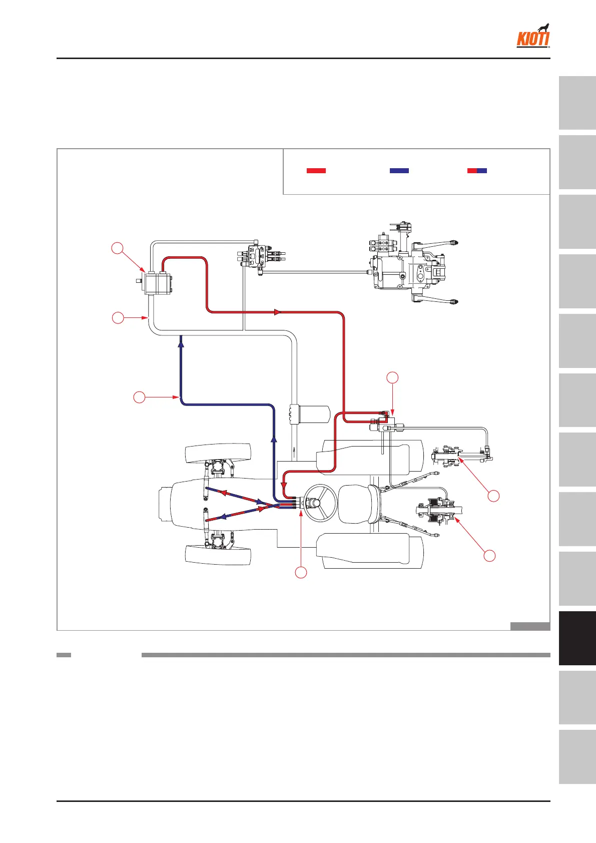
2.1 DIAGRAM FOR STEERING OPERATION
MECHANICAL
▶
The oil supplied from the gear pump (1) is sent to the
modulator (2) to provide the pressure for the operation
of PTO (3) or 4WD (4). Then, it is supplied to the steer-
ing unit (5).
T46W902A
Pressure
Return
Operating
hydraulic
pressure
(1) Gear pump
(2) Modulator valve
(3) PTO clutch pack
(4) 4WD clutch
(5) Steering unit
(6) Steering return pip
(7) Suction pipe
COMPONENTS
The oil ows to the left or right steering cylinder depend-
ing on the rotated position of the steering wheel. Then,
the other cylinder that is not supplied with oil is com-
pressed by the tie rod. The oil is return to the gear pump
suction line (7) through the return line (6) and recirculated.
RETURN
RETURN
STEERING SYSTEM - OPERATING PRINCIPLE
M32_EN_A4.indb 3 2007-02-02 오전 10:44:45