DESCRIPTION OF OPERATING SYSTEM 4-23
WARNING
To prevent loss of control of trac-
tor, never use the differential lock
at speeds above 8 km/h (5 MPH).
Never use the differential lock
when turning the tractor. When
engaged, the differential lock will
prevent the tractor from turning.
IMPORTANT
If a rear wheel spins at speed,
reduce engine speed before en-
gaging the differential lock, to
avoid shock loads to the trans-
mission.
A12O441A
The tractor is equipped with an external
position control lever. Use this lever
when connecting implements to the three-
point hitch.
WARNING
When external position control le-
ver is adjusted, the transmission
lever and PTO transmission lever
must be located in neutral
position. Pull the parking break.
The engine must be operated in
idle state. Draft control lever push
to the front side, and maintain in
floating range.
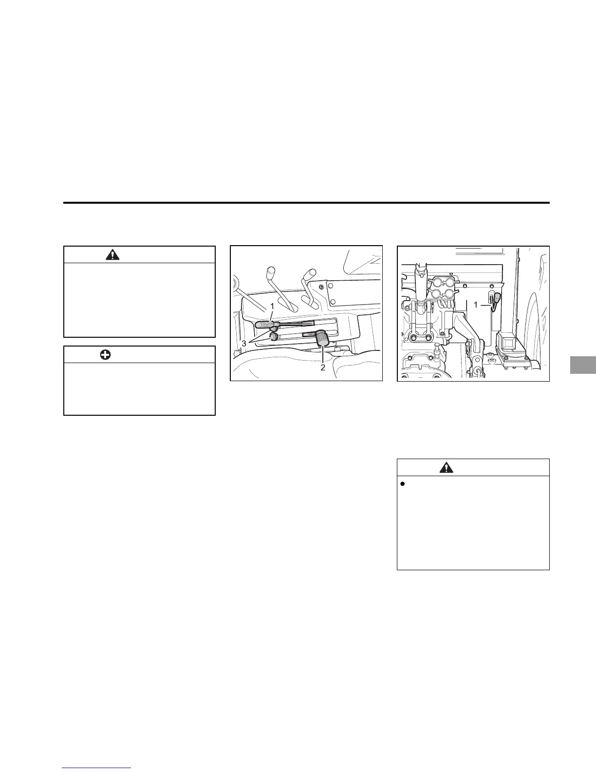
(1) External Position Control Lever
EXTERNAL POSITION CONTROL LEVER
Operating the hydraulic control lever ac-
tuates the hydraulic lift arm, which con-
trols implement height or working depth.
To lower implement, push the lever
forward; to raise it, pull the lever back.
HOW TO USE THE STOP BOLT
1. Determine a desired working position,
using the control lever.
2. Fix the stop bolt in the desired position.
3. Once the stop bolt is set, simply move
the relevant hydraulic lever forward
until it reaches the stop bolt.
POSITION CONTROL LEVERS
A12O440A
(1) Position Control Lever
(2) Draft Control Lever
(3) Stop Bolt
DK501/551