47
● Igniter (Ignition module)
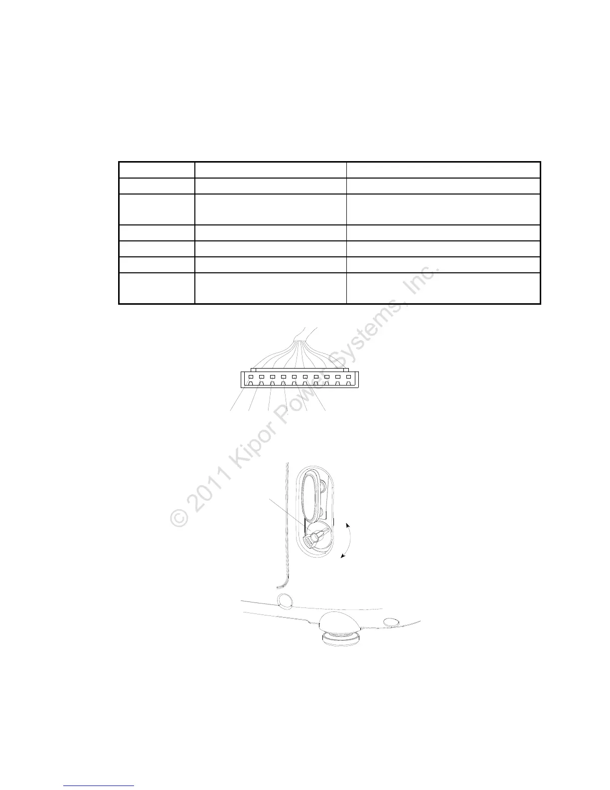
Pull off the 10P receptacle from the module. Measure the resistance by connecting one test lead
with the metal outer case of the engine and the other lead with the 10P connector.
Color Circuit unit Standard resistance
Blue Primary coil of the ignition coil 0.8-1.3Ω
Orange Oil level alarm
There should be no continuity with correct
oil level
Yellow Trigger coil 80-130Ω
Yellow/Green Ground wire Continuity
Green Igniter unit power coil winding 0.26-0.28Ω
Red Engine switch
There should be no continuity with the
switch ON, continuity with the switch OFF
兰
橙
黄黄
绿
绿
红
ON
OFF
熄火开关
(油开关)
Blue Orange Yellow Green Red
Yellow/
Green
Engine
switch
 Loading...