Do you have a question about the Kipor KG390 and is the answer not in the manual?
Highlights the critical role of correct servicing for operator safety and generator reliability.
Provides essential safety guidelines and personal protective equipment advice for maintenance.
Outlines rules for using genuine parts, special tools, and proper assembly procedures.
Details precautions for handling connectors, wiring harnesses, and electrical testing.
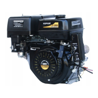
Explains where to find the engine serial number and the purpose of the bar code.
Step-by-step instructions for removing the cylinder head, including bolt tightening sequence.
Details on disassembling and reassembling the cylinder head components, including spring basis.
Procedure to measure the free length of valve springs and compare it to service limits.
How to measure the width of the valve base and check against service limits.
Instructions for cleaning and checking the cylinder cover for cracks and distortion.
Measures the external diameter of the valve stem and compares it to the service limit.
Details on measuring the inner diameter of the valve bore against service limits.
Procedure to measure the clearance between the valve bore and the valve conduct pipe.
Provides instructions and specifications for adjusting the engine's valve clearance.
Details on the crankshaft cover, including gasket and positioning pin.
Procedures for installing the piston, camshaft, and connecting rod, noting key marks and torque.
Guidance on aligning the camshaft gear and timing gear using marks for proper installation.
Method for checking bearing clearance by rotating the shaft and identifying noise or movement.
Instructions for installing piston rings and connecting rod, including manufacturer marks and orientation.
Rules for piston ring installation: marking orientation, avoiding mix-ups, and checking rotation.
Measures the inner diameter of the cylinder and compares it to the service limit.
Details on measuring the piston apron's external diameter against service limits.
Measures the clearance between the piston and the cylinder bore, including side clearance.
Measures the terminal clearance of the piston ring within the cylinder.
Procedure to measure the height of piston rings and check against service limits.
Measures the external diameter of the piston pin and compares it to the service limit.
Details on measuring the internal diameter of the piston pin bore against service limits.
Measures the clearance between the piston pin and its bore.
Measures the internal diameter of the connecting rod's small end.
Measures the internal diameter of the connecting rod's big end.
Measures the external diameter of the crankshaft's main journal.
Measures the clearance between the connecting rod big end and the crank journal.
Procedure using plastic gauge to measure crankshaft oil film and connecting rod big end clearance.
Measures the height of the camshaft lobes for wear.
Measures the external diameter of the camshaft journals.
Measures the inner diameter of the camshaft bearing and compares it to the service limit.
Provides instructions for disassembling and reassembling the meshing gear assembly of the electric starter.
Checks continuity of the electromagnetic switch's pull and hold coils and contactors.
Measures starter brush length and advises replacement if worn beyond the service limit.
Checks mica depth and provides guidance on finishing if below the limited value.
Checks conductivity between commutator sector parts, recommending armature replacement if un-conductive.
Checks insulation between the commutator and shaft, advising armature replacement if continuity exists.
Inspects meshing gear teeth for wear and checks clutch operation for free rotation.
Checks the spline gear for free movement and wear on the rotor shaft.
Checks brush movement in the holder, cleaning/replacing if resistance is noted, and checks insulation.
Checks continuity of the excitation coil between the brush lead wire and coil.
Checks continuity between the brush and starter cover to detect coil failure.
| Type | 4-stroke, OHV, single cylinder |
|---|---|
| Displacement | 389 |
| Bore x stroke | 88×64 |
| Compression ratio | 8.5:1 |
| Cooling system | Forced air |
| Ignition system | Transistorized electric ignition |
| Ignition timing | 28°B.T.D.C |
| Spark plug | F7RTC |
| Carburetor | Float type, Horizontal, butterfly valve type |
| Air cleaner | Dry Replaceable Element |
| Governor | Electronic control type (Inverter Module) |
| Lubrication system | Splash |
| Oil Capacity | 1.2 Qt (1.1 L) |
| Starting System | Electric starter |
| Stopping System | Electric ground |
| Fuel | automotive grade unleaded gasoline 87 Octane |
| Maximum horsepower | 7.7 @ 3600 RPM |