11
Chapter 6 Radio Debugging
Before test/debugging, make sure all the equipments have
been well connected to the ground.
Before test/debugging, make sure the antenna output terminal
has been connected properly to the corresponding devices and load.
The transmitter output must pass RF power attenuator before
being connected to the standard signal source/ frequency deviator/
frequency spectrum.
When testing the receiver, make sure not to conduct
transmitting operation.
When in debugging/testing/service, make sure static free
measures for human body and equipments.
6.1 Service Equipment and Software.
The following equipments and software in Table 6.1 are
necessary for the service and test of the radio.
Table 6.1 For Test and Service Equipment and Software
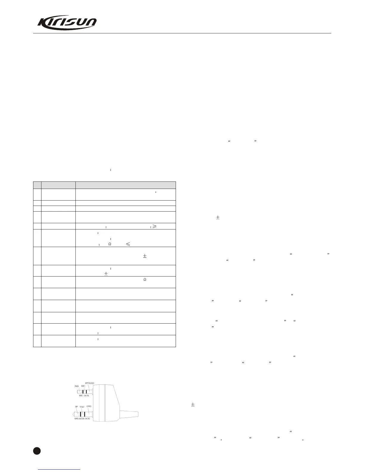
Figure 6.1 E xternal Speaker/Mic Connector Def in it io n
The equipments in item 6, 7, 8, 10, 11, and 12 can be replaced by a
comprehensive test instrument.
6.2 Debugging Items
During the course of maintenance, the radio needs to be tested
and debugged after replacing components. Some certain radio
parameters can be modified (computer mode) with our KSP 20
programming software. The modifiable parameters are as follows:
1) Frequency difference
2) TX power
3) Low battery power warning threshold
4) Squelch level
5) CTCSS frequency deviation
6) DCS frequency deviation
Debugging Procedures
a.Enter the computer test mode. Access method refers to the
instruction in 4.2 parameter setting.
b.Select the Test Mode option to enter the computer test
mode.
c.Select the options that you want to adjust and adjust the
parameters on the computer.
d.After adjustment, exit the computer test mode.
6.3 Debugging
6.3.1 VCO Modification
Turn off the power saving mode. Set the frequency at the low
frequency . In receiving status, test the PD power with the digital
multimeter. Adjust the trimming capacitor C180 to make the PD
power at 1V 0.1V.
Set the TX frequency at high frequency , press the PTT button,
test the PD power with the digital multimeter. The power should
lower than 3.5V.
6.3.2 PLL Frequency Adjustment
Under the computer test mode, select frequency tune
option and click adjustment to enter. Adjust the TX frequency
among 0~255 to the specified value. (Frequency error should less
than 200Hz.)
6.3.3 TX Frequency Adjustment
Under the computer test mode, select high power, low
frequency and click adjustment to enter. Adjust the TX power
among 0~255 to 4W. And watch the working current and make sure
it not higher than 1.5A.
Adjust high power, medium frequency , high power, high
frequency to set the TX power at 4W.
6.3.4 TX Low Power Warning
Adjust the power to 6.8V.
Under the computer test mode, select the low power
threshold , and click adjustment to enter. Adjust the figure
among 0~255 to make the red light flash.
6.3.5 Frequency Deviation Adjustment
Input 100mV, 1000Hz audio signals from the radio MIC, and
adjust the potentiometer VR2 to set the TX frequency deviation at
2.2kHz.
6.3.6 DCS TX Signal Wave Shape and Frequency
Adjustment
Under the computer test mode, select DCS wide band
modulation and click adjustment to enter Adjust the
PT558 SERVICE MANUAL
No.
1
2
3
4
5
6
7
8
9
10
11
12
13
14
Item
Computer
Programming
Software
Programming
Line
Cloning Line
DC Regulated
Power
RF power meter
Frequency Meter
Frequency
Deviator
Digital Multimeter
Audio Signal
Generator
RF power
Attenuator
Standard signal
source
Oscillograph
Audio voltmeter
Specifications
Higher than P2, compatible with IBM PC
WINDOWS 98/ME/2000/XP
KSP-20
KSPL02
KCL01
Output voltage 7.5V, Output current 5A
Test range 0.5---10W
Frequency range 100MHz500MHz
Impedance 50 SWR 1.2
Frequency range: 0.1600MHz
-6
Frequency precision: Higher than 1X10
Sensitivity: Higher than 100mV
Frequency range DC600MHz
Test range:0-- 5kHz
Input impedance:Higher than 10M /V DC,with the
ability of testing voltage, current, impedance.
Frequency range: 2---3000Hz
Output level: 1---500mV
Attenuation: 40dB or 50dB
Supporting power: Bigger than 10W
Frequency range: 10MHz---1000MHz
Output level: 0.1uV~32mV (-127dBm~ 17dBm)
Frequency range DC~20MHz
Test range 10mV~20V
Test range 10mV~10V
 Loading...