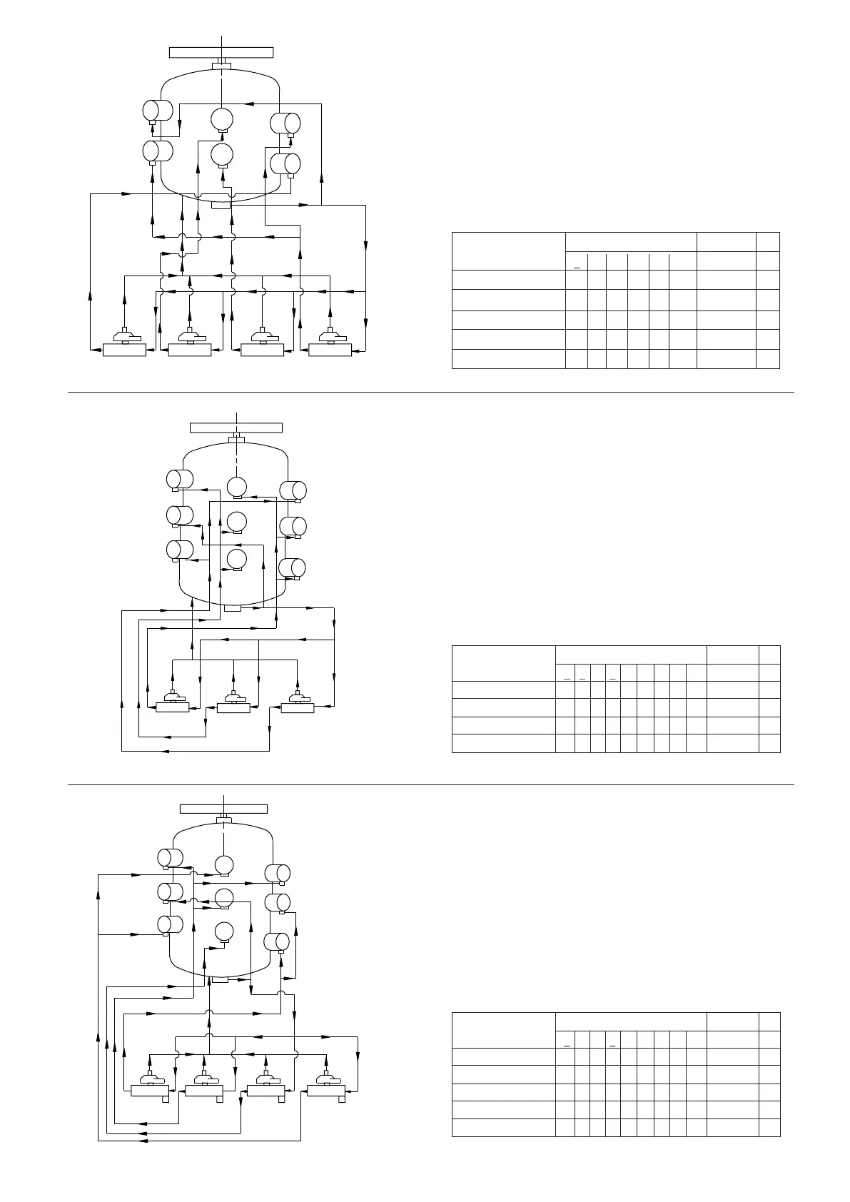
Cyl. Block. No. Capacity Ø
1 2 3 4 5 6 % -
Direct Connection 4- - - - - - -
Solenoid Valve 1 ON 4- 44- - 40 2
Solenoid Valve 2 ON 4- 444- 60 3
Solenoid Valve 3 ON 44444- 80 4
Solenoid Valve 4 ON 444444100 5
Compressor KC-51 Figure 18
Compressor KC-72 Figure 20
Cyl. Block. No. Capacity
1 2 3 4 5 6 7 8 9 %
Direct Connection - - - 4- - - - - - -
Solenoid Valve 1 ON - 4- 4- - 4- - 29 2
Solenoid Valve 2 ON - 4- 4- - 44- 43 3
Solenoid Valve 3 ON 44444- 44- 72 2.5
Solenoid Valve 4 ON 444444444100 3.5
Ø
Compressor KC-63 Figure 19
Cyl. Block. No. Capacity
1 2 3 4 5 6 7 8 9 %
Direct Connection - - - 4- - - - - - -
Solenoid Valve 1 ON - - 44- - 4- - 33 2
Solenoid Valve 2 ON 4- 4-44- 44- 67 2
Solenoid Valve 3 ON 444444444100 2
Ø
1
3
2
3 3
1 2
1 2
S.V.NO.3 S.V.NO.2 S.V.NO.1
1
3
2
4
5
6
7
8
9
HP
HP
HP
1
3
2
4
5
6
7
8
9
HP
HP
1 2 1 2
3 3 3 3
1 2 1 2
S.V.NO.4 S.V.NO.3 S.V.NO.2 S.V.NO.1
HP
1
2
3
4
5
6
1 2 1 2 1 2 1 2
S.V.NO.4 S.V.NO.3 S.V.NO.2 S.V.NO.1
3 3 3 3
17
 Loading...