Note D:
The CH3 DC Input (Alternator/Start Battery Input) can accept a 12V or 24V battery with an alternator
system. When the unit is first connected, the unit will measure the input voltage. If the voltage is > 17V, it
will assume it is connected to a 24V Input Battery/Alternator system. If the voltage detect is < 17V, it will
assume it is connected to a 12V Input Battery/Alternator system. Once detected, it will store this into the
microprocessor and it will only be erased if the Input battery is disconnected or if the measured Input
Voltage drops to < 7Vdc.
DC Input (CH2 – PV Solar Array/ Panel)
PV Input Under Voltage Shutdown
PV Input Under Voltage Recovery
PV Input Over Voltage Shutdown
PV Input Over Voltage Recovery
MPPT type (approx. 97% efficiency)
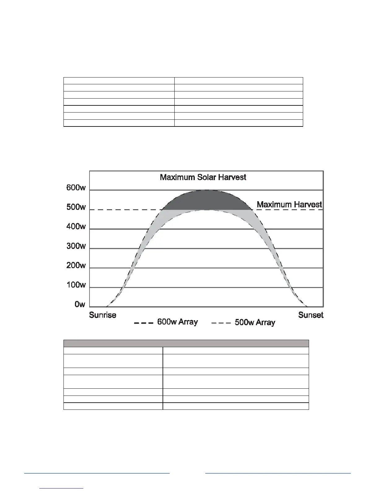
*Note: The recommended maximum solar wattage input for the Charger is 500w. You can however
“overdrive” the MPPT controller. Please note that doing this is partially an economic decision. You can
install more power than the controller can use and this will contribute to better power availability. KISAE
suggests a total maximum overdrive of 20% (total 600w). On cloudy (or intermittent sunny) days there will
be little or no power shaving and the extra power will serve the battery well with more energy harvest
earlier and later in the day.
Understanding the Display & Function Keys during normal operation
Digital Display Info: CH1
CH2 & CH3
Charging Status, Voltage, Current
Voltage
Error code E01-E08, Warning A01-02
CH3 > 12.0V (12V I/P system), > 24.0V (24V I/P
system and not charging from alternator
Charging from CH3 input (Start battery/Alternator)
CH2 > 14.5V and not charging from solar array
Charging from CH2 input (solar)
During normal operation, the display will cycle through and show CH1 battery voltage,
charging current and charging stage (‘bul’ – Bulk stage, ‘Abs’ – Absorption stage, ‘Ful – Float
stage) alternatively. When the ‘INFO’ key is pressed, it will display the other channel’s battery
voltage only
CH3 icon flashes when the input voltage is above the Flashing Voltage (> 12 on a 12V system
or > 24V on a 24V system) and it is not the source to charge the battery. It will change to solid
when it becomes the source to charge the battery.