WIRING DIAGRAMS
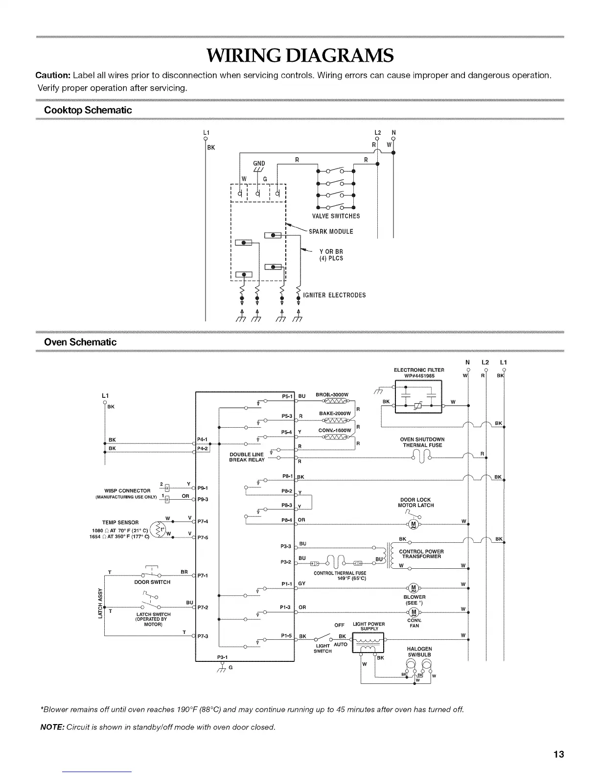
Caution: Label all wires prior to disconnection when servicing controls. Wiring errors can cause improper and dangerous operation.
Verify proper operation after servicing.
Cooktop Schematic
L1 L2 N
BK W
W GND R R
I I I
i VALVESWITCHES
I
I_""'_ SPA R K MODULE
_ _ ---IF _-_ YORBR
L j I,/pLCS
_ IGNITER ELECTRODES
P
Oven Schematic
L1
BK
RK
WISP CONNECTOR
(MANUFACTURING USE ONLY)
TEMP SENSOR
1080 _ AT 70 ° F (21 ° C) _ _'_W V
1654 £) AT 350 ° F (177 ° C)'_
T
t DOOR SWITCH
LATCH SWITCH
T
(OPERATED SY
MOTOR)
T
P4-1
P9=1
P9-3
P7-4
P7=5
P7-1
P7-2
P7=3
P5-1
P5-3
P5=4
DOUBLE LINE
BREAK RELAY
P8-1
P8-2
P8=3
P8=4
P3-3
P3=2
P1-1
P1-3
P1=5
P3-1
BU BROIL=3OOOW
R BAKE-2OOOW
3 R
ELECTRONIC FILTER
WP#4451985
OVEN SHUTDOWN
THERMAL FUSE
V
(_ DOOR LOCK
MOTOR LATCH
,B
W
W
w
W
RK
BU O O"TROLPOWER
TRANSFORMER
CONTROL THERMAL FUSE
149°F (65°0)
GM @
BLOWER
(SEE *)
CONY.
OFF LIGHT POWER FAN
SUPPLY
LIGHT AUTO
AUTO
SWITCH HALOGEN
BK 5W/BULB
W
N L2 L1
R( B_
o
*Blower remains off until oven reaches 190°F (88 C) and may continue running up to 45 minutes after oven has turned off.
NOTE: Circuit is shown in standby/off mode with oven door closed.
13