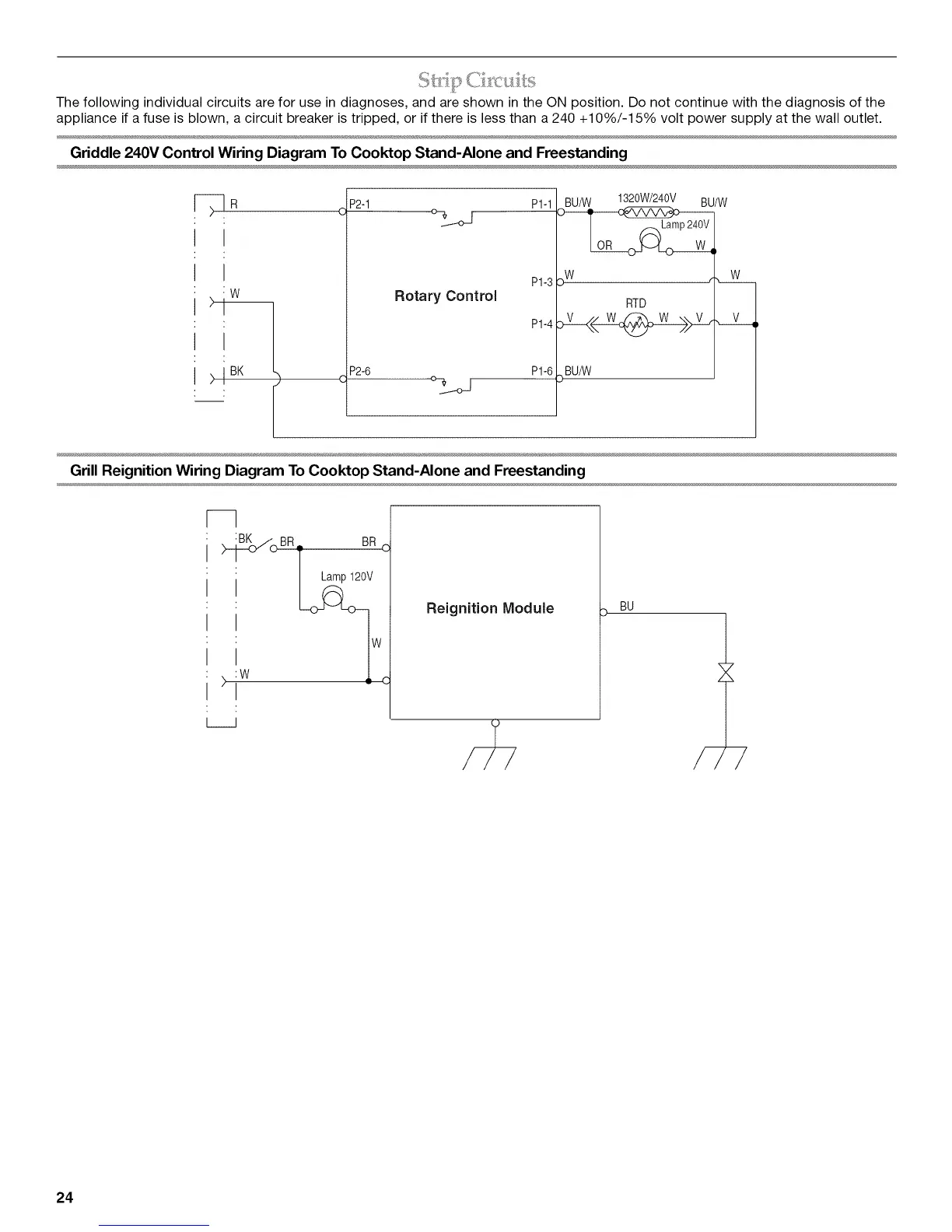
The following individual circuits are for use in diagnoses, and are shown in the ON position. Do not continue with the diagnosis of the
appliance if a fuse is blown, a circuit breaker is tripped, or if there is less than a 240 +10%/-15% volt power supply at the wall outlet.
Griddle 240V Control Wiring Diagram To Cooktop Stand-Alone and Freestanding
w
).
>1 BK
P2-1 P1-1
°%_oj
Rotary Control
P1-3
P1-4
P2-6 P1-6
o%_j
BU/W 1320W/240V BU/W
>w
RTD
BU/W
Grill Reignition Wiring Diagram To Cooktop Stand-Alone and Freestanding
--]
)w _
iJ
Reignition Module
BU
/-
24