Do you have a question about the KitchenAid KGST300 and is the answer not in the manual?
Essential safety warnings, hazard symbols, and precautions for appliance operation and service.
Explains the structure and meaning of KitchenAid gas range model and serial numbers.
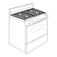
Shows the physical locations of the model/serial number label and the wiring diagram on the appliance.
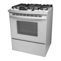
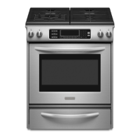
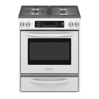
Details dimensional and technical specifications for different KitchenAid gas range models.
Covers essential gas supply requirements, codes, line sizing, and connection procedures for safe installation.
Details electrical connection requirements, including grounding, outlet types, and circuit specifications for safe operation.
Provides step-by-step instructions for converting the gas range from natural gas to L.P. gas.
Guides on how to adjust the flame size and color for surface and bake burners for optimal combustion.
Instructions for securely installing the anti-tip bracket to prevent accidental tipping of the range.
Explains the working principle of the electronic ignition system for lighting the gas burners.
Describes the importance of proper air flow around the rear panel for oven cooling and control panel temperature.
Details the operation of the cooling fan and its role in managing internal component temperatures.
Explains the function and operation of the ambient and cooling fan bimetal switches.
Describes the operation of the door lock solenoid and latch switch during self-clean cycles.
Explains the process and timing of the self-clean cycle, including door locking and heating phases.
Identifies the location of various internal components within the gas range.
Step-by-step guide for removing the control panel, ignition switches, gas valves, and bimetal switches.
Instructions for safely removing the door latch assembly from the gas range.
Procedure for removing the electronic oven control board and the touch/control panel assembly.
Steps for removing the cooktop bimetal sensor and individual surface burners or ignitors.
Instructions for safely removing the cooktop glass and vent assembly.
Step-by-step guide to remove the convection fan motor from the appliance.
Procedure for removing the oven light socket assembly.
Instructions for removing the meat probe jack from the oven.
Steps to remove the broil burner and its associated ignitor.
Procedure for removing the bake burner and its associated ignitor.
Instructions for removing the oven temperature sensor.
Steps for removing the gas distribution and safety valves assembly.
Procedure for removing a side panel to access internal components.
Instructions for removing the door switch and the power supply board.
Steps for removing the spark module and the cooling fan motor.
Guide for removing decorative glass, door handle, hinges, and oven door glass.
Step-by-step procedure for removing the oven door from the range.
Instructions for removing the oven door gasket.
Procedures for testing bimetal switches using an ohmmeter.
Steps for testing the ignition switches for proper continuity and operation.
Testing procedures for the door switch and door latch assembly using an ohmmeter.
Tests for convection fan motor resistance and safety valve continuity.
Procedures for testing gas distribution valve pressure and oven temperature sensor resistance.
Resistance tests for the cooling fan motor and broil/bake ignitors.
Procedure for testing the gas valve for pressure drops using a manometer.
Lists fault codes displayed by the oven control and their potential causes.
Detailed charts and meanings for specific fault error codes encountered on the appliance.
A guide to diagnose common oven problems, their possible causes, and solutions.
Procedure to follow after service to verify all functions operate correctly.
Steps to calibrate the oven temperature for accurate baking and cooking.
Provides schematic diagrams of the appliance's electrical connections and circuits.
Illustrates simplified circuit diagrams for various operating modes of the range.
| Fuel Type | Gas |
|---|---|
| Number of Burners | 4 |
| Oven Type | Standard |
| Ignition System | Electronic |
| Convection | No |
| Width | 30 inches |
| Burners | Sealed Burners |
| Cooktop Material | Porcelain |
| Oven Interior | Porcelain |
| Color Options | Black, White |