MOBILE HOMES
"r_'e installation of a range designed for mobile home instal- able). Secure the ANTI-TIP bracket to the wall with
Jn must conform with the Manufactured Home Construc- the two screws provided as shown in figure 4. Pro- ._=
ben and Safety Standard, Title 24 CFR, Part 3280 (formerly ceed to STEP 3. !
the Federal Standard for Mobile Home Construction and
Safety, Title 24 HUD, Part 280) or, when such standard is B. Cement or Concrete Construction:
not applicable, the Standard for Manufactured Home Instal-
1. Suitable screws for concrete construction can be
lotions 1982 (Manufactured Home Sites, Communities and obtained at the hardware store. Drill the required
Set-Ups), ANSI A225.1-1984, er with local cedes, size hole for the hardware obtained into the con-
crete at the center of the holes identified in figure 1
LOCATING THE RANGE as"FLOOR-CEMENT". Secure the ANTI-TIP
bracket to the floor. Proceed to STEP 3.
Place range where it will be well lighted. Do not set range
over holesin thefioor or otherlocationswhereitmay besub- STEP 3 - Range Installation
ject to strong drafts. Any opening in the wall behind the A. Completetheinstailationoftherangepertheinstallation
range and in the floor under the range should be sealed, instructions provided with the product.
Make sure the flow of combustion or ventilation air is not ob*
structed. B. Nign the range to its designated location and slide it
back into position. Note: A minimum clearance of 114"is
required between the range and the leveling foot that will
ANTI-TIP DEVICE engage the ANTI-TIP bracket, see figure 4.
INSTALLATION INSTRUCTIONS' c. ForSAFETY CQNSIOERATIONS as well as optimum
WAR NING: A risk of range tip over exists if the appliance is performance adjust the range so that it is level. This may
not installed in accordance with the installation instructions be checked by placing a spirit level or.a large pan of
provided. The proper use of this device minimizes the risk of water on the cooktop or the oven rack. If an adjustment
TIP-OVER. In using this device the consumer must still ob- is required pull the range forward, tip the range and re-
serve the safety precautions as stated in the USE and CARE tate the leveling feet as required.
'a,NUAL and avoid using the oven door and/or lower
awer as a step stool. D. To check the range for proper installation of the anti-tip ,
bracket: Use a flashlight and leek underneath the bet- ,-[
tom of the range to see that one of the rear leveling legs
Installation instructions are provided for wood and cement in is engaged in the bracket slot.
either floor or wall. Any other type of construction may re-
quire special installation techniques as deemed necessary E. Proceed with the remainder of the installation instrue-
to provide adequate fastening of the ANTI-TIP bracket to tions provided with the range.
the floor or wall.
STEP 1 - Locating The Bracket
A. Mark the floor or wall where either the right or left "" "'=_ "'_'
"EDGF_."of the 30" opening is to be located. '_"_" ",=" -- _"
the marked "EDGE" toward center of opening and _ .-
against the back wail. _ _ . _
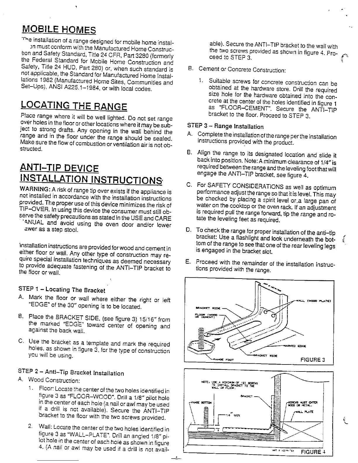
C Usethebracketasatemplateandmarktherequired _._r __
holes, as shown in figure 3, for the type of construction
you will be using. / ---,.-._,,,.,_ ,,,_-, - =_._-r ,_=c FIGURe 3
STEP 2 - Anti-Tip Bracket installation _
A. Wood Construction: _._, _,E_=:'_,,,_*._._,,=,__=_T_
1. Floor" Locate the center of the two hales identified in
figure 3 as "FLOOR-WOOD". Drill a 1/8" pilot hole ! _'"=_ _ , _,,,_..
inthe center of each hole (a nail or awl may be used ,,.,_
if a drill is net available). Secure the ANTI-TIP _,,4"MIN
L
bracket
to the floorwith the two screws provided.
2. Wall: Locate the center of the two holes identified in _--
figure 3 as "WALL-PLATE", Drill an angled 1/8" pi-
lot holeinthe center ofeachhole as shown infigure
4. (A nail or awl may be used if a drill is not avail- "' ' "_"-'" FIGURE 4