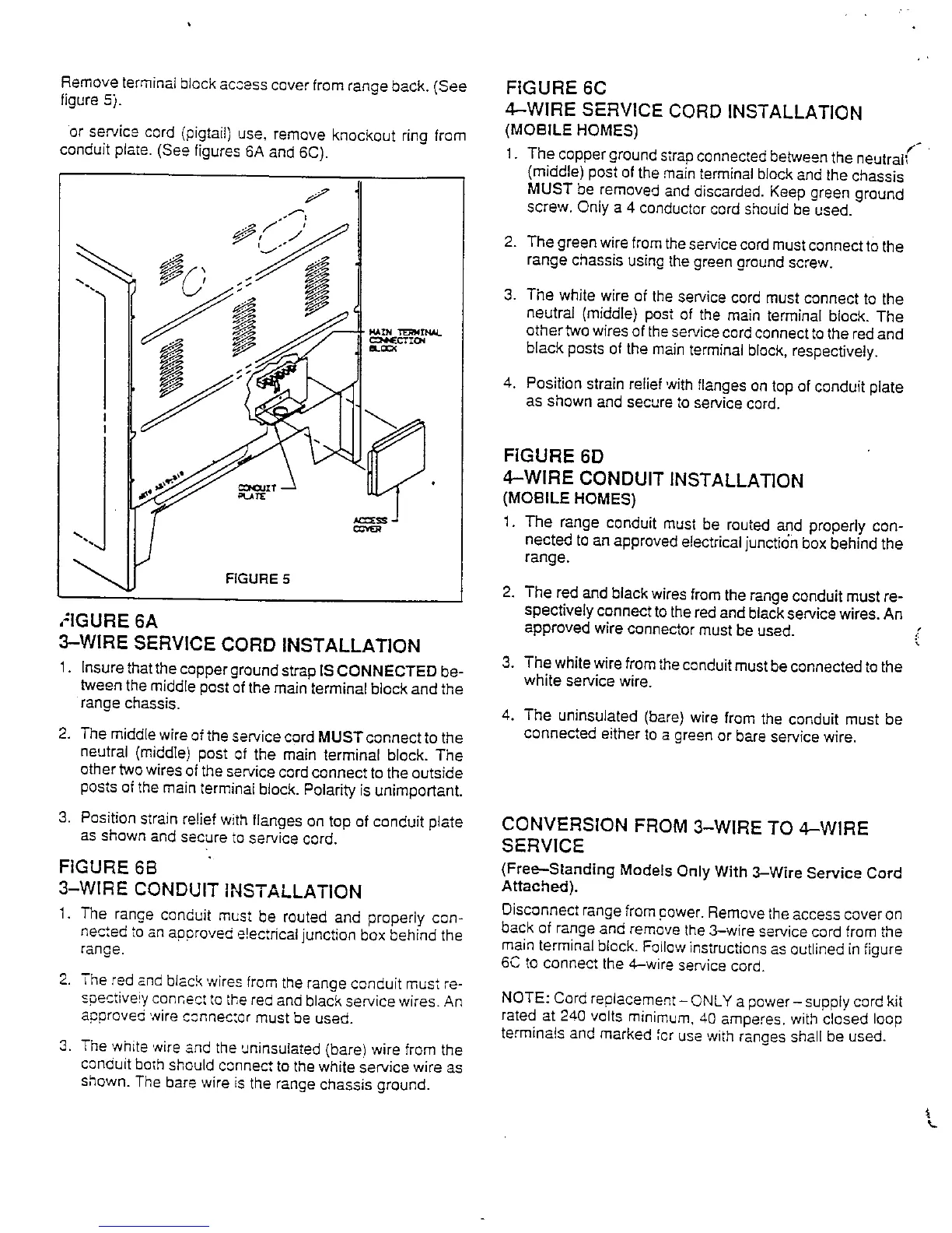
Remove terminal block access cover from range back. (See FIG URE 6C
figure 5). 4---WIRE SERVICE CORD INSTALLATION
or service cord (pigtail) use, remove knockout ring from (MOBILE HOMES)
conduit plate. (See figures 6A and 6C). 1. The copper groundstrapconnectedbetween the neutral_
(middle) post of the mainterminal blockand the chassis
MUST be removed and discarded. Keep green ground
7 screw. Only a 4 conductorcord should be used.
-* f I
_,_'./.J 2. The green wirefrom theservicecordmustconnect t0 the
range chassis using the green groundscrew.
3. The white wire of the service cord must connect to the
neutral (middle) pest of the main terminal block. The
--_ ,.,_N.r_,__ other twowires of theservicecord connecttothe red and
black posts of the mainterminal block, respectively.
4. Position strain relief with flanges on top of conduit plate
as shown and secure to service cord.
FIGURE 6D
4-WIRE CONDUIT INSTALLAT]ON
(MOBILE HOMES)
1. The range conduit must be routed and properly con-
nected to an approvede!ectriealjunction box behind the
""" range.
FIGURE5
2. The red and black wires from the rangeconduit must re-
spectively connect to thered and blackservicewires. An
,"IGURE 6A approved wire connector must be used. ,_:
3--WIRE SERVICE CORD INSTALLATION
3. The whitewirefrom theconduit mustbe connected tothe
1. Insurethatthe copper groundstrap IS CONNECTED be- white service wire.
tween the middlepost of the main terminal block and the
range chassis. 4, The uninsulated (bare) wire from the conduit must be
2. The middlewire ofthe service cord MUSTconnect to the connected either to a greenor bare servicewire.
neutral (middle) post of the main terminal block. The
other twowires ofthe service cordconnect to the outside
posts ef the main terminal block. Polarity is unimportant.
3. Position strain relief with flanges on top of conduit plate CONVERSION FROM 3-WIRE TO 4-WIRE
as shown and secure to service cord. SERVICE
FIGURE 6B (Free--Standing Models Only With 3-Wire Service Cord
3-WIRE CONDUIT INSTALLATION Attached).
1. The ranee conduit must be routed and properly con- Disconnectrange from power.Removethe access coveron
- back of rangeand remove the 3-wire service cord from the
ne_,ed _o,=napproved e!ecthcaljunction box behind the main terminal block. Followinstructionsasoutlined in figure
range. 6C to connect the 4-wire se,wicecord.
2. The red and black wires from the range conduit must re-
spective!yconnect to the red andblack service wires. An NOTE: Cord replacement- ONLY a power- supply cord kit
approved 'wire connector must be used. rated at 240 volts minimum, 40 amperes, with closed loop
terminals and marked for use with ranges shall be used.
3. The ,white',,,,ireand the uninsuiated (bare) wire from the
conduit both s,,ouldc,.,nnec,to the white service wire as
shown. The bare wire is the range chassis ground.