EasyManua.ls Logo

KKT chillers ECO122L - User Manual

KKT chillers ECO122L
39 pages
Print Icon
To Next Page IconTo Next Page
Loading...
83003502.Kc ECO_Install_Instruction_V03.odt
Page 1 of 39
Install Instructions
Models: ECO122L with IFP
ECO133L with IFP
0036
Customer Siemens Helthcare
Allee am Röthelheimpark 2
91052 Erlangen
Manufacturer ait-deutschland GmbH
Industriestraße 3
95359 Kasendorf
Germany
T +49 9228 9977 0
F +49 9228 9977 149
E info@kkt-chillers.com
W www.kkt-chillers.com
Service Center KKT chillers, Inc. Servicehotline USA:
765 Dillon Drive
Wood Dale, IL 60191
TF +1 866 517 6867 24/7 Hotline
F +1 847 734 1601
E support@kkt-chillersusa.com
Safety first:
The owner of this unit is responsible that everyone who is working on the unit observ the
safety rules and read the whole Manual/Install instructions and understand it.
A wrong or sloppy maintained unit could cause high body risk or even risk of death.
Question and Answer IconNeed help?

Do you have a question about the KKT chillers ECO122L and is the answer not in the manual?

Overview

This document outlines the installation and maintenance instructions for the KKT Chillers ECO122L and ECO133L models, which include an Interface Filter Panel (IFP). These chillers are designed to provide cooling for Siemens equipment, and proper installation and maintenance are crucial to ensure their functionality and to maintain warranty.

Function Description

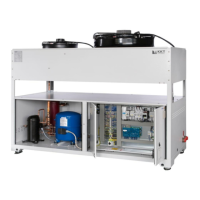
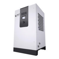
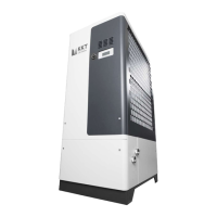
The KKT Chillers ECO122L and ECO133L are water chillers designed to cool Siemens equipment. They operate by circulating a water-ethylene glycol mixture through a closed-loop system, maintaining a stable temperature for the connected equipment. The system includes an Interface Filter Panel (IFP) which is an integral part of the cooling block and plays a role in managing the water circuit and pressure. The chillers are equipped with fans for air intake and condensers, and they operate dependently on the MR system via a "Heartbeat" signal.

Important Technical Specifications

Models: ECO122L and ECO133L, both with IFP.

Dimensions:

  • Depth: 1100 mm (43.3 inches)
  • Width: 2100 mm (84.45 inches)
  • Height: 2050 mm (80.71 inches)

Weight (Operating):

  • ECO122L: approx. 727 kg (1,603 lbs.)
  • ECO133L: approx. 780 kg (1,720 lbs.)

Weight (Transport):

  • ECO122L: approx. 1,177 kg (2,595 lbs.)
  • ECO133L: approx. 1,230 kg (2,712 lbs.)

Air Quantity:

  • ECO122L: max. 20000 m³/h
  • ECO133L: max. 25000 m³/h

Refrigerant:

  • Type: R407C
  • GWP: 1774
  • Required quantity: 13kg
  • CO2 equivalent: 23.1 t CO2
  • High-pressure switch: 31 bar

Water Circuit:

  • Water connection inlet/outlet: 2" G" female thread (internal)
  • Cold water temperature outlet: 20/19/22°C ±0.5 K (Set/min/max)
  • Cold water temperature inlet: max. 30°C
  • Operating liquid: distilled water and 35-38% Ethylene Glycol
  • Rated water capacity: min. 7.8 m³/h
  • Rated water pressure at IFP: max. 6.0 bar
  • Safety valve water circuit/Chiller: 3.0 bar
  • Volume of water circulation system: approx. 12 liters (~3.2 gal)
  • Expansion vessel: 40 L, pre-pressurized with 0.6 bar nitrogen.
  • Maximum permitted piping length between ECO Chiller and IFP: 45m (one way).
  • Recommended pipe diameter:
    • Up to 25 meters (82 ft.): 2” (R2, DN 50 or 54-mm copper)
    • Up to 45 meters (147.6 ft.): 2 1/2" (R21/2, DN 65 or 64-mm copper)

Ambient Temperature:

  • Minimum: -20°C (-4°F)
  • Maximum: +48°C (+118.4°F)
  • Temperature of surroundings (rated): 48°C

Cooling Capacity:

  • ECO122L: 45.0 kW
  • ECO133L: 60.0 kW
  • Rated cold water outlet temperature: 20°C

Power Supply:

  • Main supply ROW: 380-480V / 3Ph / 50-60Hz
  • Main supply USA: 460V / 3Ph / 60Hz
  • Control voltage: 24 VDc
  • Fluctuations in main voltage: max. -14/+10%
  • Fluctuations in frequency: max. ±1 Hz

Power Input:

  • ECO122L: max. 21 kW
  • ECO133L: max. 28.5 kW

Noise Level:

  • max. 61 db(A) at 5m (at max cooling capacity and max. ambient temperature)

Fuse:

  • Maximum 80A slow-blowing fuse for pre-fusing.

Data Transfer Cable:

  • Type: POF (Plastic Optical Fiber) or Polymer optical fiber
  • Length: 50m (164 feet)
  • Tensile strength: max. 100N (cable), max. 5N (wire)
  • Outer diameter: 8mm
  • Bend radius: minimum 12 X outer diameter (96mm or 3.77 inches)

Usage Features

Installation Site:

  • Maintain at least 100 cm (39.4 in.) clearance around all four sides for air intake and servicing/repair.
  • No roof should be installed above the chiller.
  • The air intake to the condensers on the upper third of the chiller must never be obstructed.
  • A concrete foundation or sectional steel construction is recommended, with dimensions approx. 2,300 mm (7.55 feet) long by 1,300 mm (4.26 ft) wide.
  • The cooling block must be installed on a level surface.
  • If ambient temperatures exceed 40°C (104°F), the chiller should be installed such that the switch cabinet is not fully exposed to sun radiation. Sun protection may be required.

Water Connection:

  • Only copper or stainless steel pipes are recommended. PE or PVC pipes can be used if appropriate protection measures are taken.
  • Seal European fittings using pipe sealing cord (e.g., Loctite 55), Teflon tape with anaerobic sealant, or Teflon tape with Nylog sealant.
  • The inflow is FROM the IFP, and the outflow is TO the IFP. Connections are labeled.
  • Brass fittings are used for connections on both the Chiller and IFP.

Filling the Water Circuit:

  • The system must be filled with clean distilled water and 35-38% ethylene glycol.
  • Automobile anti-freeze and propylene glycol are prohibited.
  • Use ethylene-glycol from only one manufacturer (e.g., DOWTHERM SR1-Dow Chemical, Safeflow EG - Clariant). Do not mix different manufacturers.
  • Fill the system to a pressure of min. 1.0 bar (14.5 PSI) to 1.3 bar (21.7 PSI) via the feed cock when the pump is off.
  • Static pressure at the IFP-pressure gauge (pump OFF) should be 1.7-1.8 bar if the chiller is at the same level or above the MRI, and 1.2-1.3 bar if the chiller is lower than the MRI.
  • For proper adjustment of suction pressure, the expansion vessel should have a nitrogen filling pressure of 0.6-0.8 bar.
  • The flow limiter in the IFP must be removed when using a Helium Compressor ST-7H (used on Magnetom Vida and Magnetom Sola).

Electrical Connection:

  • Follow local regulations.
  • The power supply line should not pass across the switch cabinet. Use the cable opening in the lower left-hand side of the cabinet.
  • Drilling holes into the cabinet can cause interferences with regulation electronics.
  • The grounding must be an isolated ground, connected to the ground terminal (X1) in the switch cabinet, with resistance less than 5 Ohm.
  • The piping of the chiller (supply and return) must also be grounded.
  • Do not share the ground wire with other devices.
  • Use a ground wire that complies with technical standards and minimize its length.
  • When using multiple inverters, avoid looping the ground wire.
  • The data cable (POF cable) from the Chiller connects to the RX and TX connectors on the PCB in the IFP's switch cabinet.
  • The RS485-Bus must be connected at X485 (only on IFP 090). A removed or non-working RS485-Bus will cause a communication error, and if communication is lost for over 10 minutes, the chiller will proceed with daymode.

Initial Start-up:

  • Turn on the main switch (4Q1).
  • If the pump does not start, press the reset button (black button on the control cabinet door).
  • All automatic fuses and motor protection relays are off when the unit is shipped.

Control and Operation:

  • The compressor begins running when the water temperature reaches 22°C. The chiller operates in Daymode, otherwise it will turn on at 26°C.
  • The compressor releases condenser fans when running, which are reactivated around 20 bars.
  • Fans regulate themselves according to the set condenser pressure.
  • There should be no flow if the MR is not installed, and the chiller will switch off.
  • Suction pressure should be between 1.0 bar (14.5 PSI) and 1.5 bar (21.75 PSI).
  • High pressure on the IFP should be between 4.0 bar (58 PSI) and 6.0 bar (87 PSI) in Day Mode.
  • High pressure on the IFP should be between 2.0 bar (29 PSI) and 4.0 bar (58 PSI) in Night Mode.
  • Low-pressure side should be between 6.0 bar (87 PSI) and 8.0 bar (116 PSI).
  • High-pressure side should be between 18 bar (261 PSI) and 26 bar (377 PSI).
  • Outflow water temperatures should be between 19°C (66.2°F) and 22°C (71.6°F).
  • Inflow water temperatures should be between ~21°C (69.8°F) and ~27.7°C (81.9°F) for the ECO133L, and 21°C (69.8°F) and 25.5°C (77.9°F) for the ECO122L, depending on the operating state of the MR system.
  • The outlet water temperature during Nightmode should reach 26°C.

Maintenance Features

General Maintenance:

  • The Chiller/IFP/FreeCooler must be serviced at least twice a year by a Chiller company (e.g., KKT chillers or authorized service partner).
  • Maintenance must be carried out by properly trained personnel.
  • Only genuine KKT chillers spare parts must be used.
  • The manual and other documents must not be removed from the chiller.
  • All scheduled maintenance operations detailed in the manual must be performed at the specified times. More frequent services may be required if local conditions demand it.
  • The warranty registration must be filled out and sent back within 30 days after startup.

Specific Maintenance Tasks:

  • Air Venting: Perform and repeat air venting steps until all air is bled from the system. This is crucial during initial start-up and after any component replacement involving water.
    1. Open all individual unit valves (not fill/drain valves) and all valves on the IFP Panel.
    2. Fill the system with premixed water/ethylene glycol (35-38% glycol) from the lowest point.
    3. Check static pressure at the IFP-pressure gauge (pump OFF) and refill if necessary.
    4. Vent air using the automatic air vent.
    5. If static pressure decreases, refill the water circuit.
    6. Bleed all air out of the system and chiller again (expansion vessel, pump, automatic and manual air bleeder).
    7. Start the pump for a few minutes, then switch off and vent air again.
    8. Restart the pump and monitor bleed points to ensure all trapped air is removed.
    9. Check pressure on the suction side of the pump after a few minutes and again after a few hours, refilling if necessary.
    10. Ensure the expansion vessel has the correct nitrogen filling pressure (0.6-0.8 bar).
    11. Re-check suction pressure within 24 hours.
    12. Generally, check suction pressure four times a year, even if nothing has changed.

Safety Warnings:

  • Risk of death! Voltage is still present in the control cabinet even when the MR system is turned off.
  • Risk of death! Even with the cooling block turned off, high surface temperatures can cause burns.
  • Do not pressurize the IFP with more than 2.9 bar/42 PSI when the Siemens system is connected. A too high static pressure at the IFP can cause damage to Siemens equipment, and KKT or Siemens will not cover expenses for such operations.
  • A wrong or sloppy maintained unit could cause high body risk or even risk of death.
  • Only trained and qualified personnel are permitted to install, start up, and repair the cooling block.
  • Cooling water circuit is pressurized.
  • Switch off the chiller and depressurize before servicing the cooling circuit.
  • Drain water from pipes and spare parts before shipment.
  • Nominal static filling pressure when Chiller has been switched off is about: 1-2 bar (14.5-29PSI).
  • The pressure of the expansion vessel is without counter pressure from the water/glycol – side = 0.6-0.8bar.
  • Don't handle valves while the chiller is running.
  • Ethylene glycol must be added at the rate of 35-38% of the volume of water, otherwise warranty is void.
  • The rate depends not on the local ambient temperature.
  • Don't use automotive antifreeze.
  • Voltage is continuous present at the terminals, even after the medical device has been switched off.
  • Parts in the refrigerant circuit are hot, even the Chiller has been switched off.
  • Warranty is void if manual removed from chiller.
  • Before commencing work on the unit, switch the plant to voltage-free.
  • In cases of emergency, turn off the aggregate by the main switch.
  • Work on electric and refrigerant circuits should only be performed by qualified operatives. Observe safety rules!

KKT chillers ECO122L Specifications

General IconGeneral
BrandKKT chillers
ModelECO122L
CategoryChiller
LanguageEnglish

Related product manuals