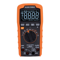
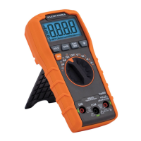
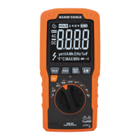
SYMBOLS USED ON LCD
~
AC Measurement DC Measurement
-
Negative DC Value
OL
Overload: Range Exceeded
Low Battery
H
Hold Active
AUTO
Auto Range Active
V
Voltage Measurement
%
Duty Cycle Mode Frequency Mode
A
Current in Amps
Ω
Resistance in Ohms
Diode Test Continuity Test
n
Nano 10
-9
°
F
Temperature in Fahrenheit
m
Milli 10
-3
F
Capacitance in Farads
µ
Micro 10
-6
M
Mega 10
6
k
Kilo 10
3
ENGLISH
H
z%
mA
A
µA
Temp
H
z%
mA
A
µA
Temp
• Safely discharge capacitor before measurement.
• Reading may take up to 60 seconds for large capacitors.
7. Frequency (Hz)/Duty Cycle < 1MHz
• Use included thermocouple and adapter.
• Do not apply voltage to thermocouple.
• Follow AC Voltage test setup.
8. Temperature: -4°
≤
°F
≤
1832°
•
Do not attempt to measure resistance on a live circuit.
5. Diode/Continuity
6. Capacitance < 200µF
H
z%
Hz
PRESS
%
COM
m
10A/250V
~
400mA/250V
~
600V MAX
Temp
H
z%
mA
A
µA
Temp
COM
m
10A/250V
~
400mA/250V
~
600V MAX
Temp
H
z%
mA
A
µA
Temp
ELECTRICAL SPECIFICATIONS
DC Voltage Measurement
Range Resolution Accuracy
400mV ~ 600V 0.1mV ~ 1V ± (0.5% + 3 digits)
Overload Protection: 600V RMS Input Impedance: > 10MΩ.
Diode:
Display shows:
• Forward voltage drop if
forward biased.
• “O.L.” if reverse biased.
3. AC/DC Current (small): < 400mA
• Attach red lead to “mAμA” input.
• Select μA or mA, and AC or DC current source.
• Current above 400mA will require fuse replacement.
4. Resistance: < 40M
Ω
FUNC.
PRESS
FUNC.
PRESS
AC
DC
Continuity:
• Display shows resistance.
• Buzzer sounds if less than 50
Ω.

 Loading...

