Do you have a question about the Klein Tools MM400 and is the answer not in the manual?
Covers AC/DC voltage and current measurement ranges, resolution, accuracy, and input impedance.
Details resistance measurement ranges, resolution, accuracy, and overload protection.
Explains parameters for diode testing and continuity checking functionality.
Provides essential warnings for safe operation, preventing injury or damage.
Guides on proper test lead connection and usage in different measurement locations.
Step-by-step instructions for measuring AC/DC voltage, including polarity notes.
Instructions for measuring AC/DC current across various ranges and lead connections.
Procedures for measuring resistance, including safety precautions.
How to perform continuity checks and interpret results, with safety warnings.
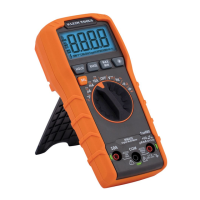
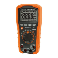
The Klein Tools MM400 is an auto-ranging digital multimeter designed for a wide array of electrical measurements. It is a versatile tool suitable for professionals and enthusiasts alike, offering a comprehensive set of functions for testing AC/DC voltage, AC/DC current, resistance, temperature, capacitance, frequency, duty-cycle, and also includes diode and continuity tests.
The primary function of the MM400 is to provide accurate and reliable electrical measurements across various parameters. Its auto-ranging capability simplifies operation by automatically selecting the most appropriate measurement range for the task at hand, eliminating the need for manual range selection in most cases.
For AC/DC Voltage measurements, the MM400 can handle voltages up to 600V. The meter defaults to AC measurement, but users can easily toggle between AC and DC modes using the "SEL" (Select) button. When measuring voltage, the meter will auto-range to display the measurement in the most appropriate range. It's important to note that when in a voltage setting with open test leads, small mV readings may appear due to noise, which is normal. Touching the test leads together to close the circuit will result in zero volts. If a negative sign appears on the LCD, it indicates reverse polarity, and the test leads should be swapped.
The multimeter also supports AC/DC Current measurements, with ranges up to 10A. Similar to voltage, the meter defaults to AC current measurement, and the "SEL" button allows switching to DC mode. For currents greater than 400mA and less than 10A, the RED test lead should be inserted into the 10A jack and the BLACK test lead into the COM jack. For mA AC/DC currents less than 400mA, the RED test lead goes into the VΩ jack. For µA DC currents less than 400µA, the RED test lead also goes into the VΩ jack. When measuring current, it is crucial to remove power from the circuit, open the circuit at the measurement point, connect the meter in-series using the test leads, and then reapply power. Users are cautioned not to attempt to measure more than 10A. For currents greater than 6A, a measurement time of 30 seconds followed by 10 minutes of recovery time is recommended.
Resistance Measurements are performed by inserting the RED test lead into the VΩ jack and the BLACK test lead into the COM jack. The function selector switch should be rotated to the Continuity/Resistance setting. The meter defaults to Continuity testing in this mode, so the "SEL" button must be pressed once to enter Resistance testing mode, indicated by the Ω icon on the display. Before measuring resistance, power must be removed from the circuit. The meter will auto-range to display the measurement. If the test leads are open or a failed resistor is under test, the display will show "OL," which is normal. It is critical not to attempt to measure resistance on a live circuit.
For Continuity Checks, the setup is the same as for resistance, with the meter defaulting to continuity testing. The continuity testing icon (a speaker symbol) should be visible. After removing power from the circuit, connecting the test leads across a conductor or circuit will trigger an audible signal if resistance is less than 50Ω, and the display will show a resistance value. An open circuit will display "OL." Again, continuity should not be measured on a live circuit.
Capacitance measurements are initiated by inserting the RED test lead into the VΩ jack and the BLACK test lead into the COM jack, then rotating the function selector switch to the Capacitance/Diode setting. The meter defaults to Capacitance testing, and the display should read "0 nF" with open test leads. If not, the "SEL" button should be pressed. Power must be removed from the circuit before connecting test leads across the capacitor. The meter will auto-range to display the capacitance.
The Diode Test is accessed from the same Capacitance/Diode setting. After ensuring the Diode icon (an arrow with a plus sign) appears by pressing the "SEL" button, test leads are touched to the diode. A reading of 200-700mV indicates forward bias, while "OL" indicates reverse bias. An open device will show "OL" in both polarities, and a shorted device will show approximately 0mV.
Frequency / Duty-Cycle measurements require the RED test lead in the VΩ jack and the BLACK test lead in the COM jack, with the function selector switch set to the Hz% setting. The meter defaults to Frequency testing. The "SEL" button toggles to Duty-Cycle testing, with the appropriate icon (Hz or %) displayed. Measurements are taken by connecting test leads across the circuit.
Temperature measurements are performed using a K-type thermocouple inserted into the VΩ and COM jacks, and the function selector switch set to the °F setting. The meter defaults to Fahrenheit, and the "SEL" button switches to Celsius. The default temperature scale can be changed by powering on the meter with the "HOLD" button depressed. To measure temperature, the thermocouple tip is brought into contact with the object, and the measurement stabilizes once thermal equilibrium is reached. The meter auto-ranges the display. It is important to remove the thermocouple before switching to other measurement functions. The included thermocouple is suitable for temperatures below 356°F / 180°C; higher temperatures require a different K-type thermocouple.
The MM400 incorporates several features to enhance usability and safety:
Proper maintenance ensures the longevity and safe operation of the MM400:
The MM400 is designed with safety in mind, featuring double insulation and a CAT III 600V safety rating, making it suitable for testing and measuring circuits connected to the distribution part of a building's low-voltage MAINS installation. Users are strongly advised to follow all warnings and instructions in the manual to ensure safe operation and prevent severe injury or death. This includes verifying meter operation before each use, never exceeding the meter's category rating, avoiding use in wet weather, inspecting test leads for damage, using only CAT III or CAT IV rated test leads, ensuring leads are fully seated, and exercising caution with voltages above 25V AC RMS or 60V DC.
| Product type | Digital multimeter |
|---|---|
| DC voltage range | 600 - 600 V |
| Measuring category | CAT III 600V |
| Placement supported | Handheld multimeter |
| Resistance resolution | 40 Ω |
| Resolution (frequency) | 50 Hz |
| Temperature measurement range | -18 - 538 °C |
| Display digits | 4000 digits |
| Battery type | AAA |
| Power source | Battery |
| Number of batteries supported | 2 |
| Depth | 152 mm |
|---|---|
| Width | 80 mm |
| Height | 45 mm |
| Weight | 231 g |