Do you have a question about the Klein Tools MM420 and is the answer not in the manual?
Details AC/DC voltage measurement ranges, resolution, and accuracy.
Details AC/DC current measurement ranges, resolution, and accuracy.
Details resistance measurement ranges, resolution, and accuracy.
Details capacitance measurement ranges, resolution, and accuracy.
Instructions for properly connecting test leads for accurate measurements.
Guidance for safe testing in CAT III/IV environments, emphasizing lead shields.
Step-by-step guide for measuring AC/DC voltage using the multimeter.
Instructions for measuring AC/DC current, including jack usage and settings.
Guide on how to measure resistance using the multimeter.
Instructions for performing continuity tests with the multimeter.
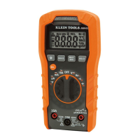
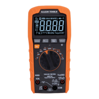
The Klein Tools MM420 is an auto-ranging, true root mean squared (True RMS) digital multimeter designed for professional and light-industrial use. It measures AC/DC voltage, AC/DC current, and resistance, and also includes functions for temperature, capacitance, frequency, duty-cycle, diode testing, and continuity checks. The device features a 3 ¾ digit, 4000-count LCD display with a backlight for clear readings in various lighting conditions.
The MM420 is equipped with a function selector switch (2) that allows users to choose between various measurement settings. The meter defaults to auto-ranging mode (AUTO), which automatically selects the most appropriate measurement range. Users can manually select a range by pressing the "RANGE" button (7) and cycling through available options. Holding the "RANGE" button for more than one second reactivates auto-ranging.
For voltage measurements (V), the meter defaults to AC. The "SEL" button (10) toggles between AC and DC modes, indicated by the AC or DC icon on the LCD. When measuring voltage, the hazardous voltage indicator (4) will appear for voltages above 30V. If a "-" appears on the LCD, it indicates reverse polarity, and the test leads should be swapped. Open test leads in voltage settings may show mV readings due to noise, which is normal; touching the leads together will measure zero volts.
Current measurements (mA, µA, 10A) also default to AC, with the "SEL" button (10) used to toggle to DC mode. To measure current, power must be removed from the circuit, the circuit opened at the measurement point, and the meter connected in-series using the test leads before reapplying power. The meter will auto-range to display the current measurement. It is crucial not to attempt to measure more than 10A. For currents greater than 6A, a measurement time of 30 seconds followed by 10 minutes of recovery time is recommended.
Resistance measurements (Ω) are accessed by rotating the function selector switch (2) to the Continuity/Resistance setting. The meter defaults to Continuity testing in this mode. To switch to Resistance testing, the "SEL" button (10) must be pressed once. Power must be removed from the circuit before measuring resistance. When test leads are open or a failed resistor is under test, the display will show "O.L." (Overload). It is critical not to attempt to measure resistance on a live circuit.
Continuity checks are performed in the same setting as resistance. The meter defaults to Continuity testing, indicated by the audible continuity icon ())) on the display. If not, the "SEL" button (10) should be pressed once. Power must be removed from the circuit. If resistance is less than 50Ω, an audible signal will sound, and the display will show a resistance value. An open circuit will display "OL". Do not attempt to measure continuity on a live circuit.
Capacitance measurements (+) are selected by rotating the function selector switch (2) to the Capacitance/Diode setting. The meter defaults to Capacitance testing, and the display should read "0 nF" with open test leads. If not, press the "SEL" button (10) once. Power must be removed from the circuit before measuring capacitance.
Diode testing is also performed in the Capacitance/Diode setting. To enter Diode testing mode, press the "SEL" button (10) once, and the Diode icon (→|) will appear on the display. Touching test leads to a diode will show a reading of 200-700mV for forward bias and "OL" for reverse bias. An open device will show "OL" in both polarities, while a shorted device will show approximately 0mV.
Frequency/Duty-Cycle (Hz%) measurements are selected by rotating the function selector switch (2) to the Hz% setting. The meter defaults to Frequency testing. To enter Duty-Cycle testing, press the "SEL" button (10) once, and the appropriate icon (Hz or %) will appear. Measurements are taken by connecting test leads across the circuit.
Temperature measurements (°F/°C) are made by inserting a K-type thermocouple into the VO (5) and COM (4) jacks, observing polarity, and rotating the function selector switch (2) to the Temperature °F setting. The meter defaults to Fahrenheit scale. To enter Celsius scale, press the "SEL" button (10) once, and the appropriate icon (°F or °C) will appear. The thermocouple tip should be in contact with the object being measured until the display stabilizes. The included thermocouple is suitable for temperatures below 356°F / 180°C; for higher temperatures, a K-type thermocouple with an appropriate range should be used. The thermocouple must be removed before switching to other measurement functions.
The MM420 includes several features to enhance usability and safety:
| Category | Multimeter |
|---|---|
| Model | MM420 |
| Display | LCD |
| AC Voltage | 600V |
| DC Voltage | 600V |
| AC Current | 10A |
| DC Current | 10A |
| Resistance | 40MΩ |
| Frequency | 10MHz |
| Continuity | Yes |
| Diode Test | Yes |
| Battery Test | Yes |
| Safety Rating | CAT III 600V |
| Backlight | Yes |
| Auto Power Off | Yes |
| Low Battery Indicator | Yes |
| Type | Digital |