EasyManua.ls Logo

Klein Tools MM325 - User Manual

Klein Tools MM325
12 pages
Print Icon
To Next Page IconTo Next Page
Loading...
INSTRUCTION MANUAL
ENGLISH
600V
10A
2M
Ω
LEAD ALERT
PROTECTION
DATA HOLD
AUDIBLE
CONTINUITY
BATTERY TEST
DIODE TEST
AUTO
POWER-OFF
Manual-Ranging
Digital Multimeter
5000573
MM325
CAT III
600V
2 m
www.GlobalTestSupply.com
Find Quality Products Online at: sales@GlobalTestSupply.com
Question and Answer IconNeed help?

Do you have a question about the Klein Tools MM325 and is the answer not in the manual?

Summary

General Specifications

Electrical Specifications

Warnings and Symbols

Safety Warnings

Crucial safety instructions and precautions to prevent injury or death during meter operation.

Symbols on Meter

Explanation of symbols displayed on the multimeter's housing for identification.

Symbols on LCD

Key to understanding the various icons and indicators shown on the digital display.

Feature Details

Function Buttons

Operating Instructions

AC Voltage Measurement

Detailed guide for measuring AC voltage, including setup and range selection.

DC Voltage Measurement

Instructions for measuring DC voltage, including settings and notes on readings.

DC Current Measurement

Procedures for measuring DC current within 200mA and 10A ranges.

Resistance Measurement

Steps for measuring resistance, including circuit preparation and range selection.

Continuity Testing

How to perform continuity tests, including audible signals and open circuit indications.

Diode Test

Procedure for testing diodes, including forward/reverse bias indications.

Battery Test

Method for testing batteries to determine their condition.

Maintenance

Battery Replacement

Steps and precautions for replacing the meter's batteries.

Fuse Replacement

Instructions and specifications for replacing internal fuses.

Cleaning, Storage, and Compliance

Cleaning Instructions

Guidelines for cleaning the multimeter using appropriate methods and materials.

Storage Recommendations

Proper procedures for storing the meter to ensure longevity and performance.

FCC & IC Compliance

Information regarding the product's compliance with FCC and IC regulations.

Warranty Information

Details pertaining to the product's warranty coverage and terms.

Disposal and Recycling

Instructions for the proper disposal and recycling of the electronic device.

Overview

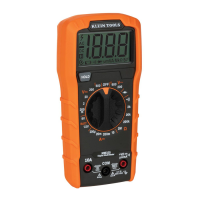
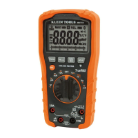
The Klein Tools MM325 is a manual-ranging digital multimeter designed for measuring AC/DC voltage, DC current, and resistance. It also features capabilities for testing batteries, diodes, and continuity.

Function Description:

The MM325 multimeter is equipped with a 2000-count LCD display, providing clear readings for various measurements. The core functionality is controlled by a Function Selector switch, which allows users to switch between different measurement modes.

For DC Voltage measurements (up to 600V), the RED test lead is inserted into the VΩ jack and the BLACK test lead into the COM jack. The Function Selector switch is rotated to the highest V DC setting, and then successively lowered to obtain higher resolution measurements. The device can measure down to 200.0mV with 0.1mV resolution.

For AC Voltage measurements (up to 600V, 50 to 60Hz), the setup is similar, with the RED test lead in the VΩ jack and BLACK in the COM jack. The Function Selector switch is rotated to the highest V AC setting, then lowered for higher resolution. The multimeter can measure down to 200.0V with 0.1V resolution. A hazardous voltage indicator will appear for voltages above 30V.

DC Current measurements are divided into two ranges. For currents between 200mA and 10A, the RED test lead is inserted into the 10A jack and the BLACK test lead into the COM jack. The Function Selector switch is set to the 10A DC setting. For currents less than 200mA, the RED test lead goes into the VΩ jack and the BLACK test lead into the COM jack, with the Function Selector switch set to the highest mA DC setting (200mA). Users are advised to remove power from the circuit, open the circuit at the measurement point, connect the meter in-series, and then apply power. The device can measure down to 200.0μA with 0.1μA resolution. A warning is given not to attempt to measure more than 10A, and for currents greater than 6A, a measurement time of 30 seconds followed by 10 minutes of recovery time is recommended.

Resistance measurements are performed by inserting the RED test lead into the VΩ jack and the BLACK test lead into the COM jack, then rotating the Function Selector switch to the highest Ω setting (2MΩ). Power must be removed from the circuit before measuring resistance. The Function Selector switch can be rotated to lower Ω settings for higher resolution. If the test leads are open or a failed resistor is under test, the display will indicate "OL." The device can measure down to 200.0Ω with 0.1Ω resolution.

Continuity checks involve inserting the RED test lead into the VΩ jack and the BLACK test lead into the COM jack, then rotating the Function Selector switch to the continuity setting. Power must be removed from the circuit. If resistance is less than 100Ω, an audible signal will sound, and the display will show a resistance value. If the circuit is open, "OL" will be displayed.

Diode Test is performed by inserting the RED test lead into the VΩ jack and the BLACK test lead into the COM jack, and rotating the Function Selector switch to the diode setting. Touching the test leads to a diode will show a reading of 200-700mV for forward bias, "OL" for reverse bias, and approximately 0mV for a shorted device. An open device will show "OL" in both polarities.

Battery Test allows for testing 1.5V and 9V batteries. The RED test lead is inserted into the VΩ jack and the BLACK test lead into the COM jack. The Function Selector switch is rotated to the 1.5V or 9V battery test setting. The BLACK lead connects to the negative terminal and the RED lead to the positive terminal of the battery. Batteries in good condition should show a voltage within approximately 10% of the rated voltage.

Usage Features:

The MM325 incorporates several user-friendly features to enhance safety and convenience:

  • Lead Alert Protection: When the Function Selector switch is rotated to a measurement setting, green Lead Alert LEDs will illuminate to confirm that the test leads are inserted into the appropriate jacks. These lights automatically turn off after 2 minutes. This feature can be disabled by powering the meter ON while holding the Backlight button, but it will reactivate by default when the meter powers OFF or the Function Selector switch is rotated.
  • Data Hold (HOLD) Button: Pressing the "HOLD" button freezes the current measurement on the display. Pressing it again releases the display and returns to live measuring.
  • Backlight Button: Pressing and holding the Backlight button for more than one second turns the backlight on or off. The backlight automatically turns off after approximately 3 minutes.
  • Auto Power-Off (APO): By default, the meter automatically powers off after 15 minutes of inactivity to conserve battery life. It can be reactivated by pressing any button. To deactivate the APO feature, power the meter ON while holding the "HOLD" button. When APO is deactivated, the Auto Power-Off symbol will not be visible on the display.
  • Safety Ratings: The multimeter is rated CAT III 600V, Class 2, with double insulation. For CAT III/CAT IV measurement locations, it is crucial to ensure the test lead shield is firmly in place to prevent arc-flash risk. For CAT II locations, these shields may be removed to allow testing on recessed conductors, but care should be taken not to lose them.
  • Polarity Indication: A "-" symbol on the display indicates negative polarity.
  • Overload Protection: "OL" is indicated on the display in case of overload, with 600V RMS protection in all settings.

Maintenance Features:

The MM325 is designed for straightforward maintenance, primarily involving battery and fuse replacement:

  • Battery Replacement: When the low battery indicator appears on the display, the batteries need to be replaced. This involves removing a screw from the battery door, replacing the two AAA batteries (observing proper polarity), and then securely fastening the battery door. Users are warned to disconnect leads from any voltage source before removing the battery door and not to operate the meter with the battery door removed to avoid electric shock.
  • Fuse Replacement: Fuses may blow if more than 200mA is applied to the VΩ jack or more than 10A is applied to the 10A jack. To access the fuses, the screw from the battery door must be removed. The blown fuses should be replaced with specific types:
    • For the VΩ (µA/mA) jack: a 200mA/600V fast-blow fuse with an interrupting rating of 1kA (Klein Cat. No. 69031).
    • For the 10A jack: a 10A/600V fast-blow fuse with an interrupting rating of 10kA (Klein Cat. No. 69032). After replacement, the battery door should be securely fastened. Again, users are warned to disconnect leads from any voltage source before accessing fuses and not to operate the meter while the back housing is removed.
  • Cleaning: The meter should be cleaned by wiping it with a clean, dry, lint-free cloth after ensuring it is turned off. Abrasive cleaners or solvents should not be used.
  • Storage: For prolonged periods of non-use, the batteries should be removed. The meter should not be exposed to high temperatures or humidity. If stored in extreme conditions outside the general specifications, it should be allowed to return to normal operating conditions before use.

Klein Tools MM325 Specifications

General IconGeneral
Diode testYes
Product typeDigital multimeter
Product colorBlack, Orange
DC current range0 - 10 A
DC voltage range0 - 600 V
Housing materialAcrylonitrile butadiene styrene (ABS)
Resistance range0 - 2000000 Ω
Measuring categoryCAT III 600V
Placement supportedHandheld multimeter
Sustainability certificatesUKCA
Battery typeAAA
Power sourceBattery
Number of batteries supported2
Weight and Dimensions IconWeight and Dimensions
Depth162 mm
Width79 mm
Height46 mm
Weight250 g

Related product manuals