·KLINGENBURG
+
-
10
8
7
6
5
4
3
2
1
9
{
9
{
{
0 - 10 Volt
0 - 20 mA
4 - 20 mA
26
24
23
22
21
20
19
18
17
25
-
S
+
-
S
+
-
+
-
S
{
{
{
{
PE
PE
PE
N
L1
S3
S2
S1
{
{
W
V
U
{
{
16
15
14
{
13
12
11
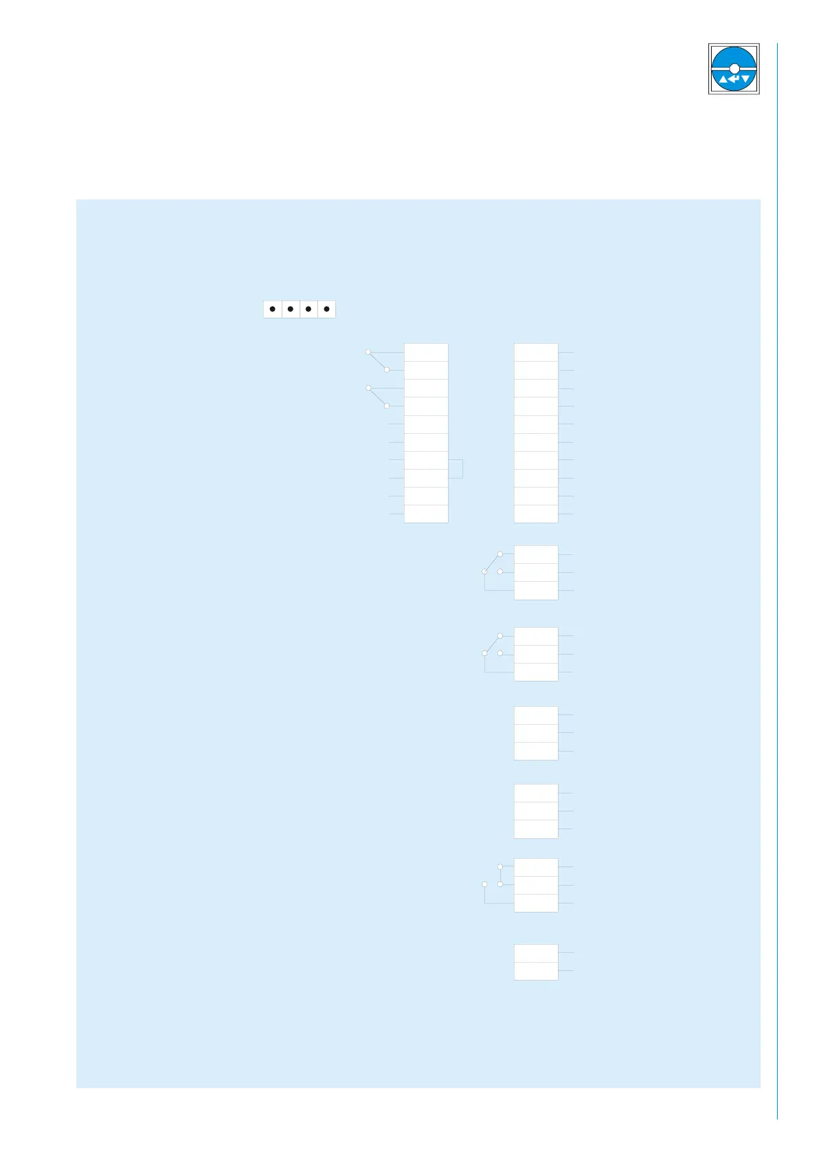
Terminal configuration of the KR4 Z / KR7 Z controller
black
brown
blue
Thermal protecton relay - motor
Rotation monitor
External control signal 0 - 10 V, 0 - 20 mA
Three-phase motor
(3x230 Volt)
Mains (230 Volt)
50 - 60 Hz
There is a supply voltage
of 24 V on the contacts 5, 7, 9
There is a supply voltage
of 10 V on the contacts 17, 20
10 Volt power supply for
sensor (e.g. enthalpy sensor)
Summer mode
Sequence switch
External control signal
0 - 10 V, 0 - 20 mA
Supply air sensor
Exhaust air sensor
Outside air sensor
Jumper
Error message
During operation S1 and
S3 closed. By occurring of
defects or net failure S2
and S3 closed
control unit release
(potential free contact)