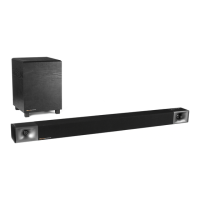
Please refer to the following drawings for assembly details:
Figures 13 and 14.
After unpacking all components, locate the KPT-402 compression driver
and horn. Attach the driver to the horn using supplied hardware.
Locate the two
1
/4"-20 screws on top of the KPT-904/940-LF. Remove the
two screws and washers. Place the KPT-402-MF unit on top of the KPT-
904/940-LF, making sure that the hole/slot as indicated by "A" in Fig. 13
lines up with the holes in the KPT-904/940-LF. Reinstall the screws and
washers. Adjust the horizontal angle as desired and tighten the screws.
Locate the KPT-Grand-HF. Locate the two
1
/4"-20 on the KPT-Grand-HF.
Remove the two screws and washers. Place the KPT-Grand-HF on top of
the KPT-402-MF and align the holes. Reinstall the screws and washers
and tighten screws as shown at "C" on Fig. 13.
Locate the
1
/4"-20 nuts as shown at "D" in Fig. 13. To adjust the vertical
angle, loosen the nuts and adjust the horns until the desired vertical
angle is achieved. Tighten the nuts.
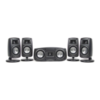
Please refer to the following drawings for assembly details:
Figures 15 and 16.
After unpacking all the components, locate the two
1
/4"-20 screws on top
of the KPT-315-LF. Remove the two screws and washers. Place the KPT-
904-HF unit on top of the KPT-315-LF, making sure that the hole/slot as
indicated by "A" in Fig. 15 lines up with the holes in the KPT-315-LF.
Reinstall the screws and washers. Adjust the horizontal angle as desired
and tighten the screws.
Locate the
1
/4"-20 bolts/nuts on both sides of the bracket as shown at "B"
in Fig. 15. To adjust the vertical angle, loosen the bolts and nuts and
adjust the horn until the desired vertical angle is achieved. Tighten the
bolts and nuts.
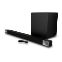
Mechanical Installation Drawings for KPT-535
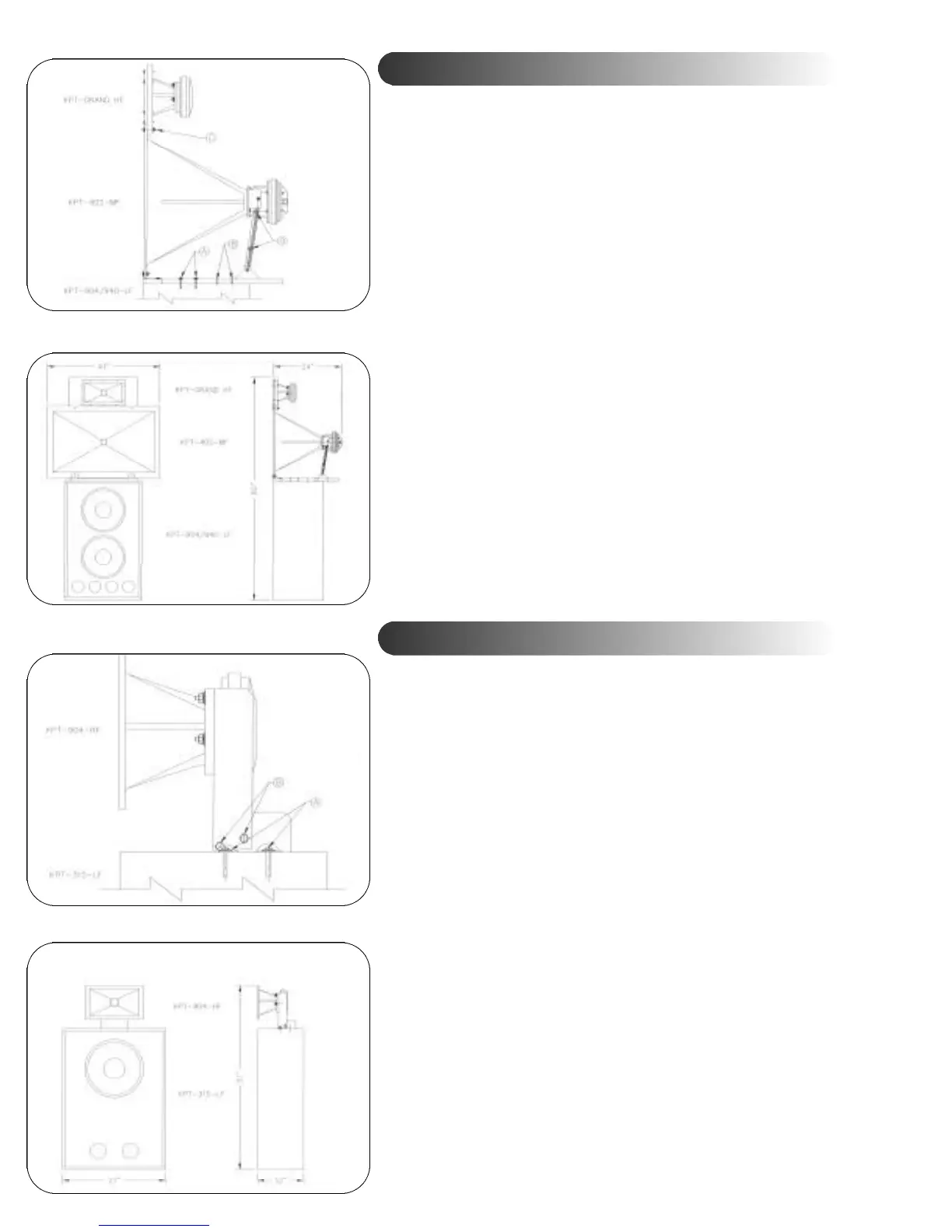
Mechanical Installation Drawings for KPT-325
Fig. 13
Fig. 14
Fig. 15
Fig. 16
 Loading...