3
BEFORE YOU BEGIN - cont'd
4. For the best results, use the pictorials to identify the various antenna components
before you begin assembly.
BOOM ASSEMBLY
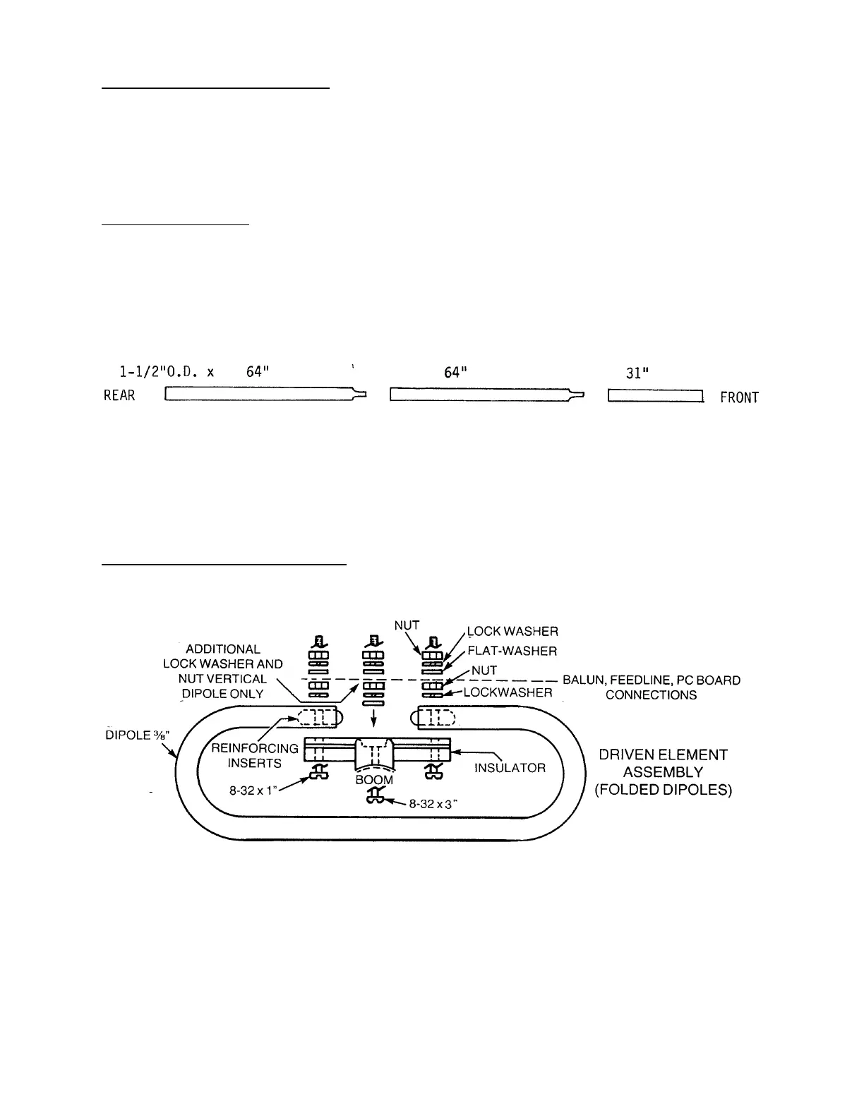
1. The end of each boom section to be assembled is marked with a letter in felt pen.
Assemble boom sections matching like letters ("A" to "A", etc.) and aligning screw holes.
Each joint requires two sets of 8-32 x 1-3/4" screws, lock washers and nuts. Hand-
tighten nuts securely. Section placement and length will follow the sketch below:
2. Mount 1" steel clip to right side of boom (when viewed from rear) using the hole
25-1/2" from rear. Secure with 6-32 x 1-3/4" hardware.
DRIVEN ELEMENT ASSEMBLY