Replacing CSC-1001 with CSC-2000/3000 Series Controllers 3 Application Guide, AN0811A Rev. A
© 2012 KMC Controls, Inc. AN0811A Rev. A
KMCControls,Inc.
19476 Industrial Drive
New Paris, IN 46553
574.831.5250
www.kmccontrols.com
info@kmccontrols.com
Replacement by CSC-3011
A CSC-3011 “universal” Reset Volume Controller
may also be used to obtain the same functionality of
CSC-1001 Constant Volume Controllers. For constant
volumeapplications, a CSC-3011 should be used in
conjunction with a normally open actuator (connect-
ed to the B port) and an SSS-1000 series ow pickup
(connected between H and L). The T port should be
exhausted. The LO Stat (“low thermostat dierential
pressure”) adjustment knob (center knob) may be set
to maintain the desired constant volume airow. (See
the Constant Volume Application illustration on the
previous page.)
EnsuretheDamperActionSelectionDialisset
properly(NormallyOpenintheseexamples).
VAVapplicationsrequiringahighlimit should be
replaced with a CSC-3011 and an RCC-1008/1108
High Selector Relay. The normally open actuator
should be connected to the B port of the RCC. The
S1 and S2 ports of the RCC should be supplied from
the B ports of the CSC-3011 and a reverse acting
thermostat. The high ow limit can be adjusted using
the LO Stat adjustment knob on the CSC-3011. An
SSS-1000 series ow pickup should be connected be-
tween the H and L ports of the CSC-3011, and the T
port should be exhausted. (See the VAV Application
with a High Flow Limit illustration on the previous
page.)
ForCSC-3011adjustmentandotherinformation,
seetheCSC-3000seriesApplicationGuide.
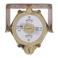
Replacement by CSC-2001/2003
CSC-2000 Series Reset Volume Controllers may be
used to obtain the same functionality of CSC-1001
Constant Volume Controllers. For constantvolume
applications, a CSC-2001/2003 should be used in
conjunction with a normally open actuator (connect-
ed to the B port) and an SSS-1000 series ow pickup
(connected between X and Y). The T port should be
exhausted. The LO adjustment knob (center knob on
the front) may be set to maintain the desired constant
volume airow. (See the Constant Volume Applica-
tion illustration on the previous page.)
VAVapplicationsrequiringahighlimit can be re-
placed with a CSC-2001/2003 and an RCC-1008/1108
High Selector Relay. The normally open actuator
should be connected to the B port of the RCC. The
S1 and S2 ports of the RCC should be supplied from
the B ports of the CSC-2001/2003 and a reverse acting
thermostat. The high ow limit can be adjusted us-
ing the LO adjustment knob on the CSC-2001/2003.
An SSS-1000 series ow pickup should be connected
between the X and Y ports of the CSC-2001/2003, and
the T port should be exhausted. (See the VAV Ap-
plication with a High Flow Limit illustration on the
previous page.)
ForCSC-2001/2003adjustmentandotherinforma-
tion,seetheCSC-2000seriesApplicationGuide.
 Loading...