CSP-4702 1 Installation Guide
Installation Guide
Analog Differential-Pressure VAV Controller/Actuator
CSP-4702
Mounting
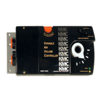
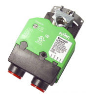
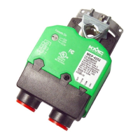
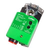
Illustration 1—Overview (Direct-Coupled Mounting)
approximately 5° may provide tight
damper shut-o.
3. Align the actuator and slide it onto the shaft.
4. Leaving a small gap between the actuator and
mounting surface to prevent any binding, nger-
tighten the nuts on the V-bolt.
5. Insert the provided (HMO-4002) non-rotation
bracket into the slot at the base of the actuator
and secure the non-rotation bracket with two #8
or #10 self-tapping screws.
6. Evenly tighten the V-bolt nuts (30–35 in-lb.).
7. If desired, use a 7/64-inch hex key wrench to
loosen and position the end-stop screw.
NOTE: The two holes at the top of the actuator
are NOT for use in direct-coupled
applications. (They are for remote
mounting, such as with the optional HLO-
4001 Crank Arm Kit.)
NOTE: For VAV applications with the analog
CTE-5202 thermostat, see the CTE-5202
Applications Guide. For static pressure
controller applications, see the CSP-
4702 Static Pressure (Bypass) Control
Application Guide.
The CSP-4702 mounts directly to 1/4- to 5/8-inch (6 to
16 mm) round shafts or 1/4- to 7/16-inch (6 to 11 mm)
square shafts.
1. Ensure the damper can move freely through its
entire range of motion, and x any binding before
installing the actuator. Turn the damper blade to
its fully closed position.
2. Press (to the right) and hold the gear disengage-
ment lever (see Illustration 1), rotate the actuator
to the fully closed position, and release the lever.
NOTE: Depending on the damper-seal design,
backing the actuator o its stop
HMO-4002
Non-Rotation
Bracket
Mounting
Surface
5.312
(134.9)
Adjustable Stop
Min/Max
Flow Limit
Meter Taps
Min/Max
Flow
Setting
Pots
Open &
Close
LEDs
2.50
(63.5)
2.812
(71.4)
2.60
(66.0)
Gear
Disengagement Lever
1.563
(39.7)
∆
P Ports
Barbed
Connections
for 1/4" FR
Tubing
Removeable Conduit Fitting
with 1/2" NPS Threaded Hole
Mounting .........................................................................................................1
Wiring Connections .........................................................................................2
Rotation Direction ...........................................................................................2
Air Pressure Connection ...................................................................................2
Min. and Max. Flow Limits ...............................................................................3
Limits Set at the CSP-4702 ...........................................................................3
Limits Set at the Thermostat .........................................................................3
Operation Test ..................................................................................................3
Maintenance ....................................................................................................3
Troubleshooting ...............................................................................................4
No Rotation ..................................................................................................4
Wrong Rotation Direction or Stroke Range ..................................................4
No Pressure Output Signal ...........................................................................4
Wiring Issues ................................................................................................4
Static Pressure Control .....................................................................................4
More Information .............................................................................................4
Important Notices ............................................................................................4