CSP-4702 2 Installation Guide
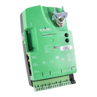
Rotation Direction
The CSP-4702 is factory-set for counterclockwise to
close. To reverse the direction (with the conduit cover
removed), move the jumper to the CW position.
Wiring Connections
1. Loosen the screw on the conduit ing and lift up
to remove the ing.
2. Using a utility knife or drill, cut the red plug
to accept wiring or replace the plug with an
application-specic ing.
NOTE: The red plug (or similar ing) protects
internal components from debris, helping to
ensure long actuator life.
3. Thread wires through the plugged opening and
connect to the terminal block as shown.
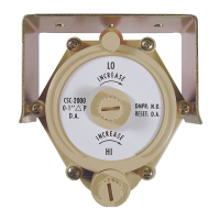
4. Make the air pressure connections (see Air
Pressure Connection on page 2), set MIN/
MAX ow (see Min. and Max. Flow Limits on
page 3), and change the rotation direction (see
Rotation Direction on page 2) as needed.
5. Reinstall the conduit ing and tighten the screw.
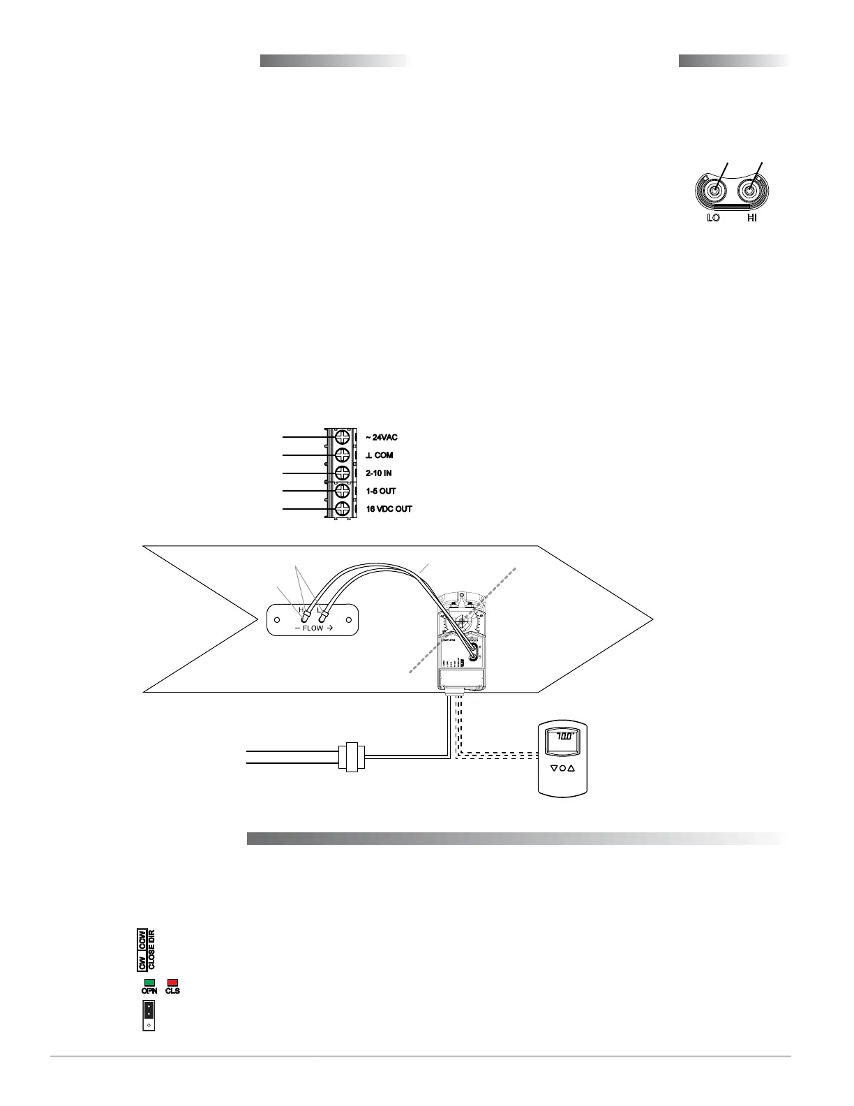
Air Pressure Connection
Connect the CSP-4702 to a dierential pressure ow
sensor with 1/4-inch OD x 0.040-inch wall FR instru-
ment and control tubing:
1. Connect the “HI” port to the
(high side) “H” of the sensor.
2. Connect the “LO” port to the
(low side) “L” of the sensor.
NOTE: For use as a static pressure controller, see
the CSP-4702 Static Pressure (Bypass)
Control Application Guide.
NOTE: For VAV applications, the SSS-1000 series
dierential pressure ow sensor must be
mounted with the arrow pointing in the
direction of the air ow. To connect to 1/4-
inch tubing from the CSP-4702, an SSS-100x
dierential pressure ow sensor requires
a 3/8" to 1/4" barb union adapter and 1"
of 3/8" OD x 0.062 “FR” tubing for both
connections (as shown in the illustration).
An SSS-101x sensor does not require the
3/8" tubing or adapter.
NOTE: All tubing should be free of kinks and
restrictions.
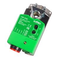
NOTE: For about 15 seconds after power is applied,
no rotation occurs and one or both of the
LEDs will ash. The Close LED illuminates
(solid red) when the actuator is closing. The
Open LED illuminates (solid green) when
opening. When the actuator reaches the end
of rotation or the mechanical stop, the LED
may stay illuminated a brief time if the
called for condition remains unsatised.
~24 VAC (Class 2 Only) Power
2–10 VDC Thermostat Signal (Input)
1–5 VDC Air Pressure Signal (Output)
16 VDC Power to Thermostat (Output)
Common (Power, Input, Outputs)
Illustration 2—Connections
Illustration 3—Rotation Indicators and Jumper
To
“H”
To
“ L”
CCW = Jumper on Upper 2 Pins
CSP-4702
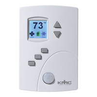
24 VAC CTE-5202
(Used in VAV
applications but
not in static
pressure bypass
applications)
Damper
SSS-100x Sensor
1/4-Inch Tubing
SET
POINT
3/8" Tubing
3/8" to 1/4" Union Adapters