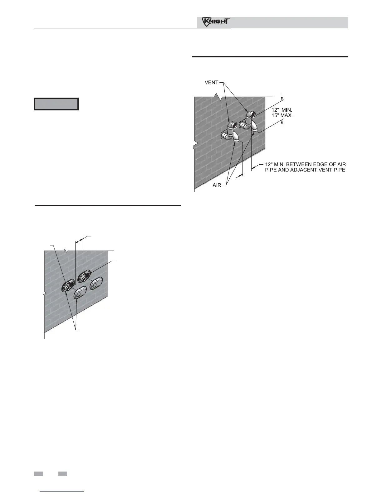
Figure 4-5A Multiple Vent Terminations (must also
comply with Figure 4-1A)
All vent pipes and air inlets must
terminate at the same height to avoid
possibility of severe personal injury,
death, or substantial property damage.
Multiple vent/air terminations
1. When terminating multiple Knight boilers terminate
each vent/air connection as described in this manual
(FIG. 4-5A).
2. Place wall penetrations to obtain minimum clearance
of 12 inches between edge of air inlet and adjacent vent
outlet, as shown in FIG. 4-5A for U.S. installations. For
Canadian installations, provide clearances required by
CSA B149.1 Installation Code.
3. The air inlet of a Knight boiler is part of a direct vent
connection. It is not classified as a forced air intake
with regard to spacing from adjacent boiler vents.
WARNING
Figure 4-5B Alternate Multiple Vent Terminations w/Field
Supplied Fittings (must also comply with Figure 4-1B)