Presence detector Mini
■ Select a vibration-free installation location. Vibrations can lead to unwanted switching.
■ Avoid interference sources in the detection area. Interference sources, e.g. heaters, vent-
ilation, air conditioners, and cooling light bulbs can lead to unwanted detections.
If necessary, the detection field can be limited using the push-on cover in order to minim-
ize the influence of interference sources.
Only for "Comfort" version:
■ Mounting near electric consumers, radiators, cooling systems or outside walls can have a
negative effect on the temperature measurement.
Aligning the device
■ When mounting, align the device so that the brightness sensor (10) is not facing the win-
dow (Figure 7).
Already pay attention to correct alignment when mounting the appliance box and support-
ing frame.
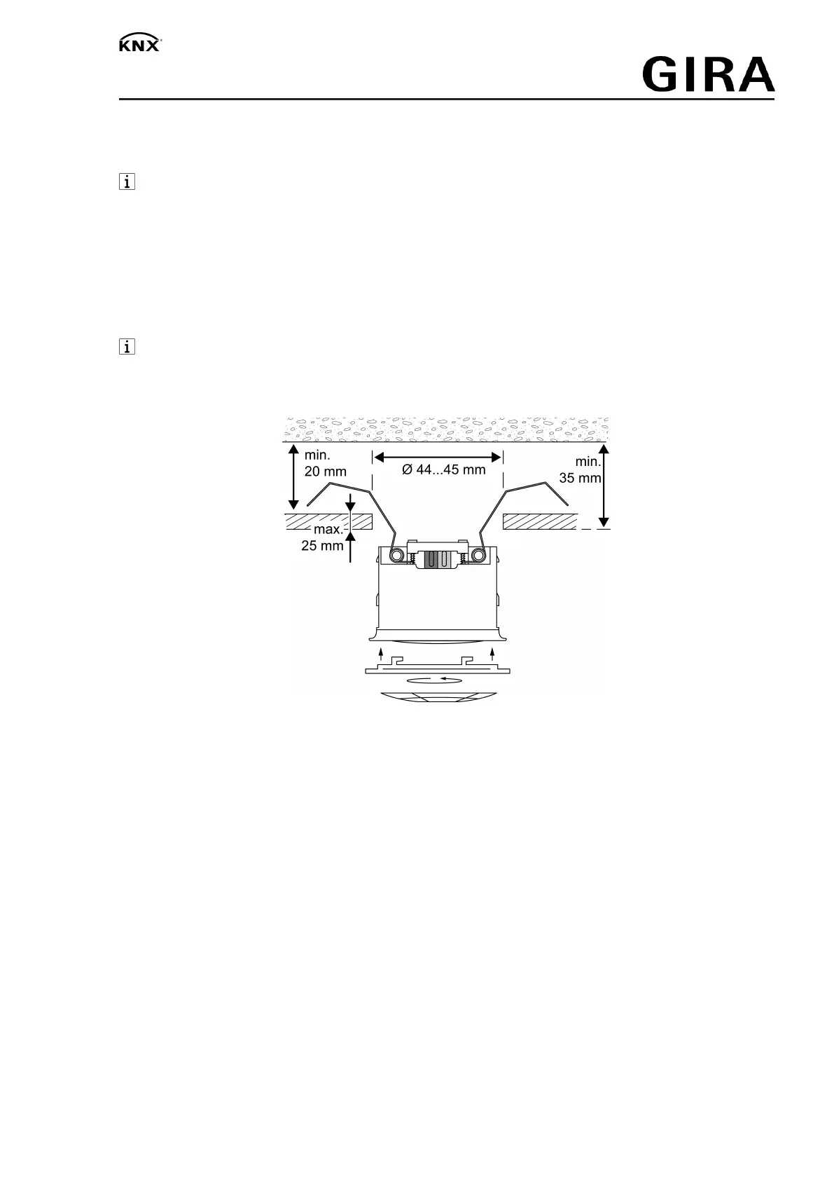
Connecting and fitting the device in the suspended ceiling
Figure8
The environment in the suspended ceiling must be dry.
Max. thickness of the suspended ceiling approx. 25 mm. Installation depth min. 35 mm. Dis-
tance between concrete ceiling and suspended ceiling min. 20 mm.
Ceiling cut-out 44...45 mm.
■ Connect bus line.
■ Clamp bus line with cable fixation (9).
■ Bend back the spring clamps (3) and push the presence detector (1) into the suspended
ceiling.
■ Attach the large design ring (5) and rotate it in clockwise direction.
■ If required: Cut out the cover (6) and clip it into the design ring (5).
8 / 13
32589822 10867613 25.02.2020

 Loading...
