13/KODAK M-SERIES PROJECTORS
the heat-absorbing filter into the light path at the still-frame
function. Since the film isn't then moving, it needs the
additional protection of the still-mode heat-absorbing filter—
otherwise, the film may burn if you keep one frame in the
light path too long.
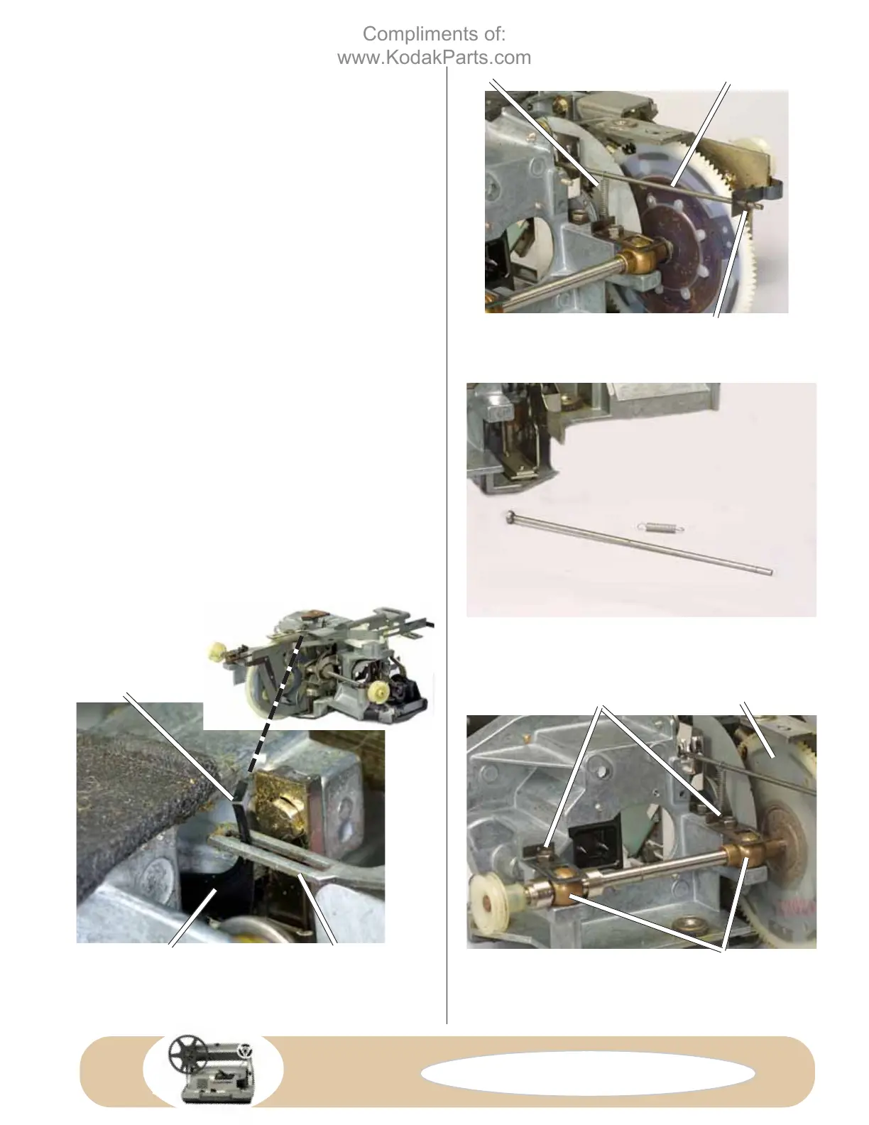
The position of the snap ring on the still-mask changeover
rod provides an adjustment, Fig. D38—the snap-ring
position controls the movement of the still-mask changeover
rod. The adjustment then determines if the heat-absorbing
filter is fully in the light path in the still-frame mode—and
completely out of the light path at the other modes.
You lose the adjustment when you remove the snap ring. So
note the position of the snap ring prior to disassembly,
Fig. D38. The snap ring is normally around 1/4" from the
end of the still-mask changeover rod. Make a note or a
sketch of the snap-ring position. Then:
1. Disconnect the coil spring from the still-mask changeover
rod, Fig. D38. Remove the spring from the projector.
2. Pull out the still-mask changeover rod toward the top of
the mechanism. The still-mask changeover rod passes
through a slot in the still-frame lever.
3. Straighten the arm of the super 8/regular 8 mask, Fig.
D40, so it will pass through the slot in the tab as you lift out
the drive-cam assembly.
4. Loosen the 2 screws that hold the spring clamps for the
cam-shaft brass bearings, Fig. D41. Swing aside the spring
clamps and lift out the cam assembly, Fig. D41.
C
AUTION: Be careful to prevent the regular-8 and
super-8 followers, Fig. D42, from coming out at this
stage. Projectors with both regular 8 and super 8 have two
SPRING CLAMPS
CAM-SHAFT BEARINGS
IN-AND-OUT CAM
STILL-FRAME CHANGEOVER ROD
SNAP RING
SPRING
SUPER 8/REGULAR 8 MASK
FLATTEN HERE
FIG. D39 Still-mask changeover rod and
spring removed.
TAB ON FILM-
SELECTOR SLIDE
FIG. D38 Bottom of mechanism.
FIG. D40 Coupling to the super-8/regular-8
mask.
FIG. D41 Loosen the screws holding the spring
clamps to remove the cam assembly.
Compliments of:
www.KodakParts.com
 Loading...