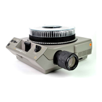
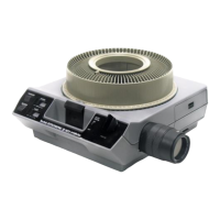
29/KODAK M-SERIES PROJECTORS
BLACK AND WHITE MOTOR WIRES
FORWARD/
REVERSE
ARM
ECCENTRIC
POWER LEADS
SWITCH
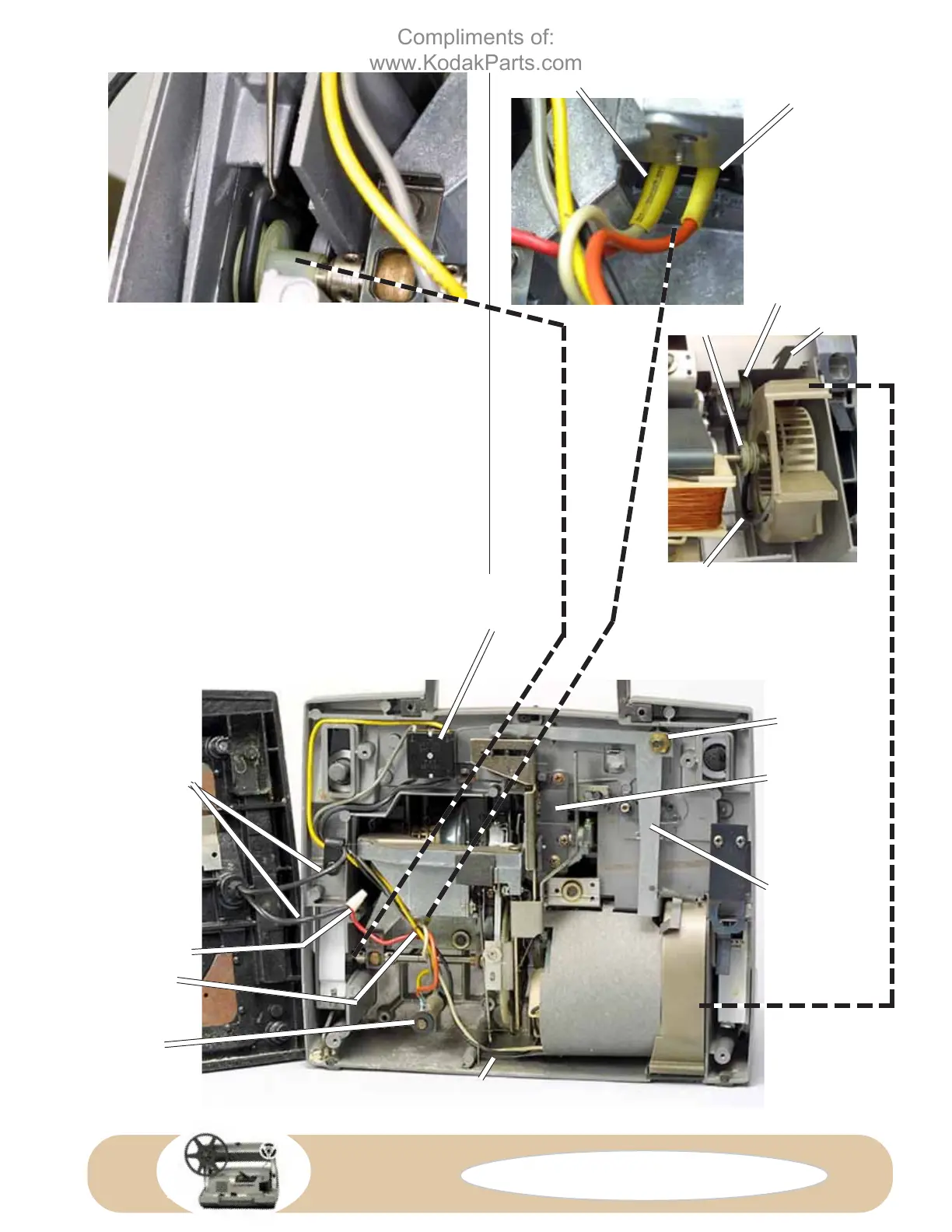
FIG. D103 Connecting the belt to the cam-
shaft pulley.
FIG. D104
Connections to
the lamp socket.
RED AND WHITE LEADS
RED LEAD
FIG. D105 Motor installed.
FIG. D106 Mecanism completely
installed housing, back view.
FAN PULLEY
PULLEY ON
SHUTTER-DRIVE
SHAFT
METAL TAB
BELT
WIREWOUND
RESISTOR
GUIDE
4. Replace the three screws holding the mechanism.
T
IP: We mentioned earlier that some screws go through
rubber grommets. Unless the grommet has a metal
washer, it wants to turn or tear. Apply a drop of shutter oil to
the screw or to the grommet, Fig. D102 (Fig. D102 shows
one of the motor screws). You can then tighten the screw
without turning the grommet.
5. Connect the rubber belt to the cam-shaft pulley, Fig.
D103.
6. Seat the wirewound resistor, Fig. D106, and replace the
long screw (remember, only the projectors using the 120V
lamp and having two lamp brightness levels use the resistor).
7. Replace the remaining screws holding the guide, Fig.
D106.
8. Replace the lamp leads to the lamp housing, Fig. D104.
Remember to first replace the insulator for the lead that has
two wires.
UPPER WIRE
CLIP
WIRE TIE
Compliments of:
www.KodakParts.com
 Loading...