Do you have a question about the Koden MDC-1810P and is the answer not in the manual?
Details how document changes are managed and recorded.
Operator safety, RF radiation hazard, and high voltage warnings.
Safety precautions for maintenance, dust, and static electricity.
Explains the meaning of standard symbols like Warning, Alarm, Caution.
Explains manual structure, scope, and how to navigate its content.
Describes radar system design, component classification, and EMC testing.
Details component units for models and lists software types and applications.
Itemized list of standard components for MDC-1810P and MDC-1820P.
Lists spare parts, installation materials, and optional accessories.
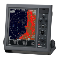
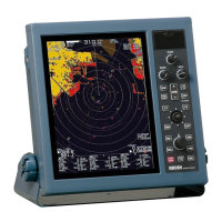
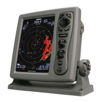
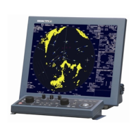
Technical details of the radar antenna and display units.
Specifications for ATA and AIS optional features.
Serial data formats, power supply, and environmental resistance.
Safe distances from compasses and component dimensions/weights.
Guidelines for unpacking, inspection, unit placement, and cable routing.
Step-by-step guide for installing transceiver, aerial, and display units.
Initial system adjustments, tuning, and optional item configuration.
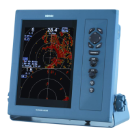
Overview, control layout, operation descriptions, and initial power-on.
Core functions like range, pulse, gain, anti-clutter, and measurement tools.
Factors affecting range, image reading, and false echoes.
Menu settings for radar functions, display, and adjustments.
System configuration, EPA, ATA, and AIS functions.
Steps to activate and choose graphic display items.
Procedure for registering or modifying navigation lines and map data.
Details required for service and equipment self-check features.
First-line faultfinding steps and diagnostic charts.
Procedures for on-board maintenance, including fuse replacement.
Guidelines for monthly and yearly checks and cleaning procedures.
Details of IEC61162-1 serial data sentences.
Formats for TTM, OSD, and RSD radar data sentences.
Input requirements for various system interfaces.
| Antenna Rotation Speed | 24 rpm |
|---|---|
| Range Resolution | 20 m |
| Operating Temperature | -15°C to +55°C |
| Display Size | 10.4 inch |
| Display Type | LCD |