TP-5867 11/0268 Section 8 Disassembly/Reassembly
7. Install the exhaust system. See Figure 8-15.
a. Secure the lower portion of the exhaust duct to
the alternator exhaust support with 1/4-20
hardware.
b. Secure the engine exhaust muffler to the
engine. Do not final tighten the mounting
hardware.
c. Secure the muffler mounting tab to the
alternator exhaust support with 3/8-16
hardware.
d. Install the exhaust duct top. Secure the
exhaust duct top to the exhaust duct bottom
with four 1/4-20 x 0.625 in. bolts and washers.
e. Torque the nuts securing the engine muffler
flange to the engine to 88 in. lb. (10 Nm).
TP56328
1
2
3
4
5
6
1. Exhaust duct, top
2. Engine muffler
3. 1/4-20 hardware
4. Exhaust duct, bottom
5. 1/4-20 x 0.625 in. bolts and 1/4 washers
6. 3/8-16 hardware
Figure 8-15 Exhaust Muffler Duct
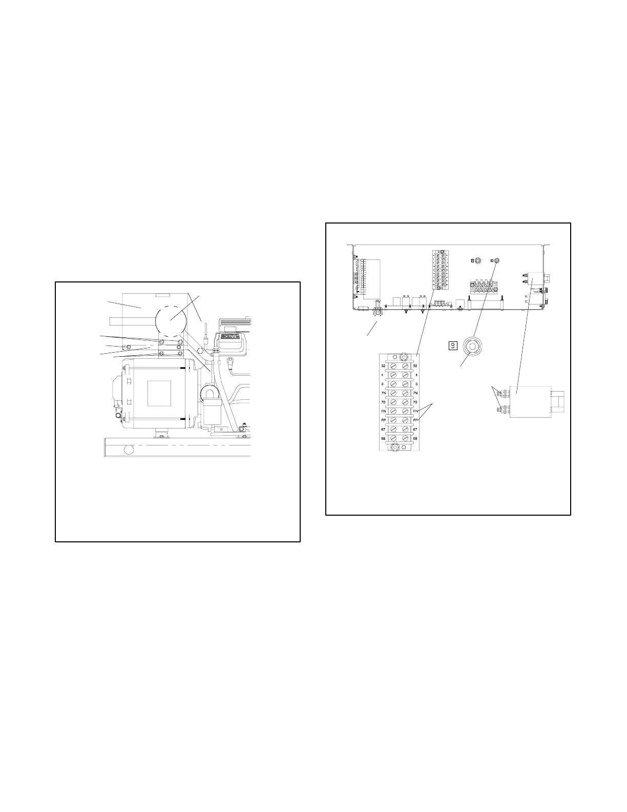
8. Reconnect leads to the controller.
a. Insert the leads from the alternator assembly
into the convoluted conduit leading to the
controller.
b. Connect the speed sensor harness to the
controller. See Figure 8-16 for the plug
location.
c. Route brush leads FP and FN into the controller
and connect them to the controller terminal
strip. See Figure 8-16.
d. Reconnect the alternator leads.
A-358076A-D
4
1
3
2
1. Speed sensor harness connection
2. L0 lead connection point
3. Circuit breaker connections
4. Brush leads FP and FN terminal block connections
Figure 8-16 ControllerTop View, Typical